Motion User Guide
- Welcome
- What’s new
-
- Intro to basic compositing
-
- Intro to transforming layers
-
- Intro to transforming layers in the canvas
- Transform layer properties in the canvas
- Transform tools
- Change layer position, scale, or rotation
- Move a layer’s anchor point
- Add a drop shadow to a layer
- Distort or shear a layer
- Crop a layer
- Modify shape or mask points
- Transform text glyphs and other object attributes
- Align layers in the canvas
- Transform layers in the HUD
- Transform 2D layers in 3D space
-
- Intro to behaviors
- Behaviors versus keyframes
-
- Intro to behavior types
-
- Intro to Parameter behaviors
- Audio behavior
- Average behavior
- Clamp behavior
- Custom behavior
- Add a Custom behavior
- Exponential behavior
- Link behavior
- Logarithmic behavior
- MIDI behavior
- Add a MIDI behavior
- Negate behavior
- Oscillate behavior
- Create a decaying oscillation
- Overshoot behavior
- Quantize behavior
- Ramp behavior
- Randomize behavior
- Rate behavior
- Reverse behavior
- Stop behavior
- Track behavior
- Wriggle behavior
-
- Intro to Simulation behaviors
- Align to Motion behavior
- Attracted To behavior
- Attractor behavior
- Drag behavior
- Drift Attracted To behavior
- Drift Attractor behavior
- Edge Collision behavior
- Gravity behavior
- Orbit Around behavior
- Random Motion behavior
- Repel behavior
- Repel From behavior
- Rotational Drag behavior
- Spring behavior
- Vortex behavior
- Wind behavior
- Additional behaviors
-
- Intro to using generators
- Add a generator
-
- Intro to image generators
- Caustics generator
- Cellular generator
- Checkerboard generator
- Clouds generator
- Color Solid generator
- Concentric Polka Dots generator
- Concentric Shapes generator
- Gradient generator
- Grid generator
- Japanese Pattern generator
- Lens Flare generator
- Manga Lines generator
- Membrane generator
- Noise generator
- One Color Ray generator
- Op Art 1 generator
- Op Art 2 generator
- Op Art 3 generator
- Overlapping Circles generator
- Radial Bars generator
- Soft Gradient generator
- Spirals generator
- Spiral Drawing generator
- Use Spiral Drawing onscreen controls
- Star generator
- Stripes generator
- Sunburst generator
- Truchet Tiles generator
- Two Color Ray generator
- Save a modified generator
-
- Intro to filters
- Browse and preview filters
- Apply or remove filters
-
- Intro to filter types
-
- Intro to Color filters
- Brightness filter
- Channel Mixer filter
- Color Adjustments filter
- Color Balance filter
- Example: Color-balance two layers
- Color Curves filter
- Use the Color Curves filter
- Color Reduce filter
- Color Wheels filter
- Use the Color Wheels filter
- Colorize filter
- Contrast filter
- Custom LUT filter
- Use the Custom LUT filter
- Gamma filter
- Gradient Colorize filter
- HDR Tools filter
- Hue/Saturation filter
- Hue/Saturation Curves filter
- Use the Hue/Saturation Curves filter
- Levels filter
- Negative filter
- OpenEXR Tone Map filter
- Sepia filter
- Threshold filter
- Tint filter
-
- Intro to Distortion filters
- Black Hole filter
- Bulge filter
- Bump Map filter
- Disc Warp filter
- Droplet filter
- Earthquake filter
- Fisheye filter
- Flop filter
- Fun House filter
- Glass Block filter
- Glass Distortion
- Insect Eye filter
- Mirror filter
- Page Curl filter
- Poke filter
- Polar filter
- Refraction filter
- Ring Lens filter
- Ripple filter
- Scrape filter
- Sliced Scale filter
- Use the Sliced Scale filter
- Sphere filter
- Starburst filter
- Stripes filter
- Target filter
- Tiny Planet filter
- Twirl filter
- Underwater filter
- Wave filter
-
- Intro to Stylize filters
- Add Noise filter
- Bad Film filter
- Bad TV filter
- Circle Screen filter
- Circles filter
- Color Emboss filter
- Comic filter
- Crystallize filter
- Edges filter
- Extrude filter
- Fill filter
- Halftone filter
- Hatched Screen filter
- Highpass filter
- Indent filter
- Line Art filter
- Line Screen filter
- MinMax filter
- Noise Dissolve filter
- Pixellate filter
- Posterize filter
- Relief filter
- Slit Scan filter
- Slit Tunnel filter
- Texture Screen filter
- Vignette filter
- Wavy Screen filter
- About filters and color processing
- Publish filter controls to Final Cut Pro
- Using filters on alpha channels
- Filter performance
- Save custom filters
-
- Intro to 3D objects
- Add a 3D object
- Move and rotate a 3D object
- Reposition a 3D object’s anchor point
- Exchange a 3D object file
- 3D object intersection and layer order
- Using cameras and lights with 3D objects
- Save custom 3D objects
- Guidelines for working with 3D objects
- Working with imported 3D objects
-
- Intro to 360-degree video
- 360-degree projects
- Create 360-degree projects
- Add 360-degree video to a project
- Create a tiny planet effect
- Reorient 360-degree media
- Creating 360-degree templates for Final Cut Pro
- 360-degree-aware filters and generators
- Export and share 360-degree projects
- Guidelines for better 360-degree projects
-
- Intro to settings and shortcuts
-
- Intro to Keyboard shortcuts
- Use function keys
- General keyboard shortcuts
- Audio list keyboard shortcuts
-
- Tools keyboard shortcuts
- Transform tool keyboard shortcuts
- Select/Transform tool keyboard shortcuts
- Crop tool keyboard shortcuts
- Edit Points tool keyboard shortcuts
- Edit shape tools keyboard shortcuts
- Pan and Zoom tools keyboard shortcuts
- Shape tools keyboard shortcuts
- Bezier tool keyboard shortcuts
- B-Spline tool keyboard shortcuts
- Paint Stroke tool keyboard shortcuts
- Text tool keyboard shortcuts
- Shape mask tools keyboard shortcuts
- Bezier Mask tool keyboard shortcuts
- B-Spline Mask tool keyboard shortcuts
- Transport control keyboard shortcuts
- View option keyboard shortcuts
- HUD keyboard shortcuts
- Inspector keyboard shortcuts
- Keyframe Editor keyboard shortcuts
- Layers keyboard shortcuts
- Library keyboard shortcuts
- Media list keyboard shortcuts
- Timeline keyboard shortcuts
- Keyframing keyboard shortcuts
- Shape and Mask keyboard shortcuts
- 3D keyboard shortcuts
- Miscellaneous keyboard shortcuts
- Touch Bar shortcuts
- Move assets to another computer
- Work with GPUs
- Glossary
- Copyright

Work with the Motion Path behavior
The following tasks demonstrate how to customize the Motion Path behavior.
Change the shape of the motion path
With an applied Motion Path behavior selected in the Layers list, Timeline, or Behaviors Inspector, do any of the following:
In the Behaviors Inspector in Motion, click the Path Shape pop-up menu, then choose a shape option.
If Path Shape is set to Open Spline or Closed Spline, double-click the motion path in the canvas to add control point points, and then edit the points. See Intro to editing control points.
If Path Shape is set to Circle, Rectangle, or Wave, drag the transform handles in the canvas.
If Path Shape is set to Geometry, modify the shape of the source geometry.
Use geometry for a motion path shape
You can use a shape animated with behaviors or keyframes as the source for a motion path. This includes animated transforms (a shape changing its location in the canvas) and animated control points (a shape changing its shape due to keyframed control points).
In Motion, import (or draw) the shape to use as the path source.
With an applied Motion Path behavior selected, open the Behaviors Inspector, then choose Geometry from the Path Shape pop-up menu.
The Shape Source well appears in the Inspector and HUD.
From the Layers list, drag the shape you created in step 1 into the Shape Source well, and when the pointer becomes a curved arrow, release the mouse button.
A thumbnail of the shape appears in the well and the shape is used as the source shape for the motion path.
Note: You can disable the source shape in the Layers list (by deselecting its activation checkbox) so that the source shape is not visible in your project.
Select another geometry source for a motion path shape
In Motion, with an applied Motion Path behavior selected, open the Behaviors Inspector, click the To pop-up menu (located next to the Shape Source well), then choose the object to use as the motion path’s shape source.
Note: To align the rotation of the object to the shape of its motion path, you can apply the Snap Alignment to Motion behavior (in the Basic Motion behaviors subcategory).
Move the object and its motion path
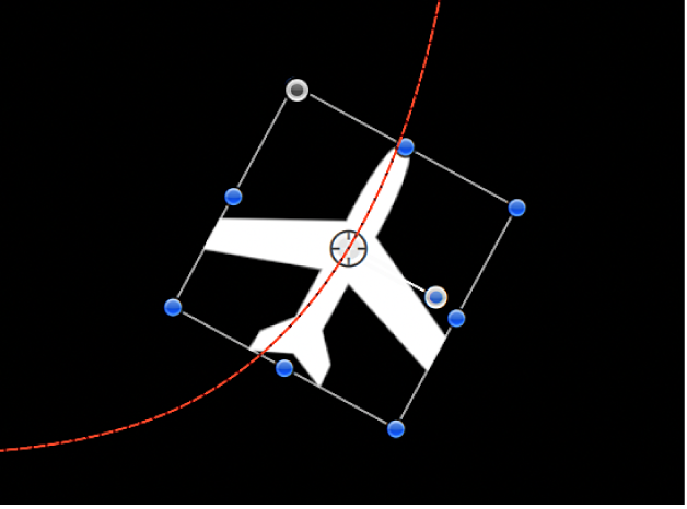
In the Layers list or canvas in Motion, select the object (not the Motion Path behavior), then drag the object in the canvas.
Note: To move the object and its motion path when Path Shape is set to Geometry, select the source object, then move the object in the canvas.
Distance the object from the path
By default, the object is locked to the motion path by its anchor point.

In the canvas toolbar in Motion, click and hold the transform tools pop-up menu, choose Anchor Point, then drag the anchor point in the canvas.
For more information on using the Anchor Point tool, see Move a layer’s anchor point.
Note: A separate Offset parameter lets you offset the starting location of the object on the motion path (but does not offset the object from the path).
Use the Custom Speed parameter
In the Layers list in Motion, select an applied Motion Path behavior.
In the Behaviors Inspector or HUD, click the Speed pop-up menu, then choose Custom.
The Custom Speed parameter control becomes available. By default, a keyframe is set at the first and last points of the behavior to create an animation of 0 percent to 100 percent, where at 0 the object is at the beginning of the path, and at 100 the object is at the end of the path. This is the same velocity used with the Constant preset.
Press A to turn on keyframe recording.
Note: When keyframe recording is on, all keyframeable parameter value sliders are tinted red, to remind you that any value change entered creates a keyframe.
Move the playhead to the position where you want to create a keyframe, then enter a percentage value in the Custom Speed field.
For example, a value of 90 moves the object 90 percent of the way through the motion path.
Continue moving the playhead and adding keyframes to obtain the result you want, then press A again to turn off keyframe recording.
Note: If you change the Speed parameter to a preset (such as Constant) after creating a custom speed, the custom velocity channel is ignored but remains intact.
Adjust a motion path in 3D space
The easiest way to modify a motion path in 3D space is to add a camera to your project and manipulate the path in a modified camera view.
If there’s no camera in your Motion project, add a camera by doing one of the following:
In the toolbar, click Add Object, then choose Camera from the pop-up menu.
Choose Object > New Camera (or press Option-Command-C).
Note: If none of your project groups are set to 3D, a dialog appears asking if you want to switch your 2D groups to 3D groups. Click Switch to 3D to allow the camera to affect the groups.
Do one of the following:
Click the pop-up menu in the upper-left corner of the canvas (the default option is Active Camera), then choose a camera view. This example uses the Top view.
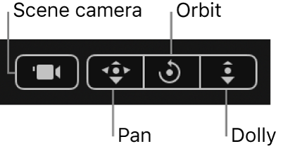
With the Active Camera (or another camera view) selected, drag in the Orbit tool (the center tool in 3D view tools in the upper-right corner of the canvas) to rotate the camera manually to a new view.

Note: If you use the 3D view tools with any camera selected, you are moving the camera, not just changing the camera view.
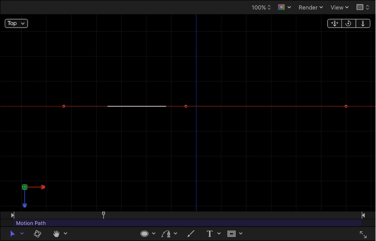
Depending on the camera view, the object on the path might not be visible. For example, if the object has not been rotated in X or Y space and you are working in Top view, the camera is looking down perpendicularly (on the Y axis) on the object. The motion path and its points are still visible (as long as the Motion Path behavior is selected).
In the following image, the motion path appears flat when viewed from above—the affected object only moves in X and Y space.

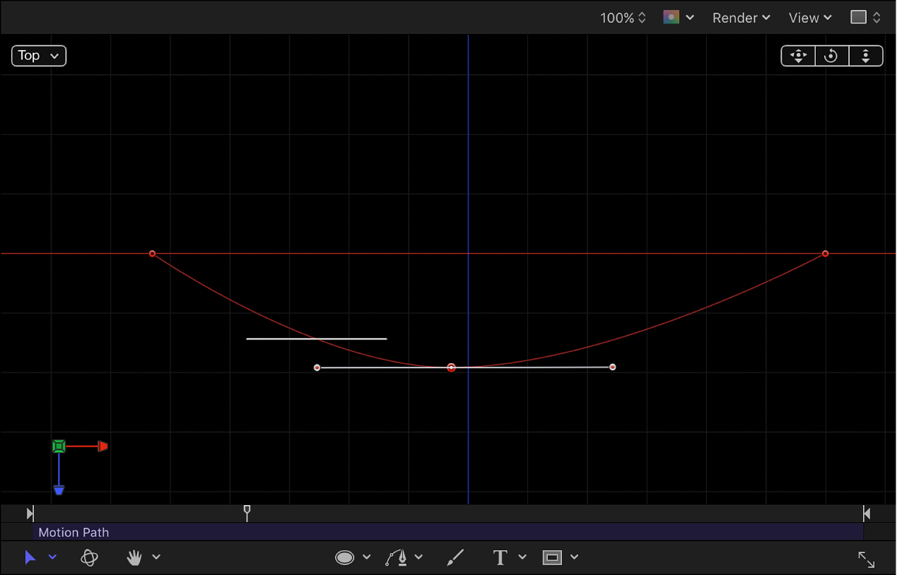
Drag a control point up or down to adjust the object in Z space.
In the following image, the path is no longer flat—the affected object moves in X, Y, and Z space.

To enter specific values for the control point locations, click the Control Points disclosure triangle in the Motion Path behavior parameters. The first value field is X, the second value field is Y, and the third value field is Z.
To reset the camera view, do one of the following:
Double-click the 3D view tool that you previously adjusted. For example, if you dragged the Orbit tool to rotate the current camera, double-click the Orbit tool to reset the camera.
If you chose (or modified) a default camera view (such as Top, Right, Left, and so on), choose Active Camera from the Camera menu, or choose View > 3D View > Active Camera.
With the camera selected, click the reset button in the Properties Inspector.
For more information about working with cameras in a 3D project, see Intro to 3D cameras.
Download this guide: PDF