Scalable mRNA and siRNA Lipid Nanoparticle Production Using a Parallelized Microfluidic Device
- PMID: 34189917
- PMCID: PMC10726372
- DOI: 10.1021/acs.nanolett.1c01353
Scalable mRNA and siRNA Lipid Nanoparticle Production Using a Parallelized Microfluidic Device
Abstract
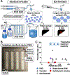
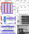
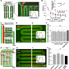
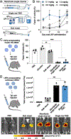
A major challenge to advance lipid nanoparticles (LNPs) for RNA therapeutics is the development of formulations that can be produced reliably across the various scales of drug development. Microfluidics can generate LNPs with precisely defined properties, but have been limited by challenges in scaling throughput. To address this challenge, we present a scalable, parallelized microfluidic device (PMD) that incorporates an array of 128 mixing channels that operate simultaneously. The PMD achieves a >100× production rate compared to single microfluidic channels, without sacrificing desirable LNP physical properties and potency typical of microfluidic-generated LNPs. In mice, we show superior delivery of LNPs encapsulating either Factor VII siRNA or luciferase-encoding mRNA generated using a PMD compared to conventional mixing, with a 4-fold increase in hepatic gene silencing and 5-fold increase in luciferase expression, respectively. These results suggest that this PMD can generate scalable and reproducible LNP formulations needed for emerging clinical applications, including RNA therapeutics and vaccines.
Keywords: gene therapy; lipid nanoparticles; mRNA; siRNA.
Conflict of interest statement
Complete contact information is available at:
The authors declare the following competing financial interest(s): J.M.W. is a paid advisor to and holds equity in Scout Bio and Passage Bio; he holds equity in Surmount Bio; he also has sponsored research agreements with Amicus Therapeutics, Biogen, Elaaj Bio, Janssen, Moderna, Passage Bio, Scout Bio, Surmount Bio, and Ultragenyx, which are licensees of Penn technology. J.M.W. and L.W. are inventors on patents that have been licensed to various biopharmaceutical companies and for which they may receive payments. S.J.S., S.Y., D.I., and M.J.M. are inventors on a patent related to this work filed by the Trustees of the University of Pennsylvania (63/131,008). D.W. is an inventor on several patents related to this work filed by the Trustees of the University of Pennsylvania (11/990,646; 13/585,517; 13/839,023; 13/839,155; 14/456,302; 15/339,363; and 16/299,202). The remaining authors declare that they have no conflicts of interest.
Figures


Similar articles
-
Production of siRNA-Loaded Lipid Nanoparticles using a Microfluidic Device.J Vis Exp. 2022 Mar 22;(181). doi: 10.3791/62999. J Vis Exp. 2022. PMID: 35404350
-
Lipid Nanoparticle Formulations for Enhanced Co-delivery of siRNA and mRNA.Nano Lett. 2018 Jun 13;18(6):3814-3822. doi: 10.1021/acs.nanolett.8b01101. Epub 2018 May 8. Nano Lett. 2018. PMID: 29694050
-
Development of a Microfluidic-Based Post-Treatment Process for Size-Controlled Lipid Nanoparticles and Application to siRNA Delivery.ACS Appl Mater Interfaces. 2020 Jul 29;12(30):34011-34020. doi: 10.1021/acsami.0c05489. Epub 2020 Jul 15. ACS Appl Mater Interfaces. 2020. PMID: 32667806
-
Microfluidic technologies and devices for lipid nanoparticle-based RNA delivery.J Control Release. 2022 Apr;344:80-96. doi: 10.1016/j.jconrel.2022.02.017. Epub 2022 Feb 17. J Control Release. 2022. PMID: 35183654 Free PMC article. Review.
-
Microfluidic production of mRNA-loaded lipid nanoparticles for vaccine applications.Expert Opin Drug Deliv. 2022 Oct;19(10):1381-1395. doi: 10.1080/17425247.2022.2135502. Epub 2022 Oct 20. Expert Opin Drug Deliv. 2022. PMID: 36223174 Review.
Cited by
-
Lipid-mRNA nanoparticles landscape for cancer therapy.Front Bioeng Biotechnol. 2022 Oct 31;10:1053197. doi: 10.3389/fbioe.2022.1053197. eCollection 2022. Front Bioeng Biotechnol. 2022. PMID: 36394007 Free PMC article. Review.
-
Hydroxycholesterol substitution in ionizable lipid nanoparticles for mRNA delivery to T cells.J Control Release. 2022 Jul;347:521-532. doi: 10.1016/j.jconrel.2022.05.020. Epub 2022 May 23. J Control Release. 2022. PMID: 35569584 Free PMC article.
-
Understanding the effects of ethanol on the liposome bilayer structure using microfluidic-based time-resolved small-angle X-ray scattering and molecular dynamics simulations.Nanoscale Adv. 2024 Mar 25;6(8):2166-2176. doi: 10.1039/d3na01073b. eCollection 2024 Apr 16. Nanoscale Adv. 2024. PMID: 38633055 Free PMC article.
-
Kinetically Controlled Polyelectrolyte Complex Assembly of microRNA-Peptide Nanoparticles toward Treating Mesothelioma.Adv Mater. 2024 Jun;36(24):e2314367. doi: 10.1002/adma.202314367. Epub 2024 Apr 4. Adv Mater. 2024. PMID: 38532642
-
Influence of ionizable lipid tail length on lipid nanoparticle delivery of mRNA of varying length.J Biomed Mater Res A. 2024 Sep;112(9):1494-1505. doi: 10.1002/jbm.a.37705. Epub 2024 Mar 15. J Biomed Mater Res A. 2024. PMID: 38487970
References
-
- Setten RL; Rossi JJ; Han S. p. The Current State and Future Directions of RNAi-Based Therapeutics. Nat. Rev. Drug Discovery 2019, 18, 421–446. - PubMed
-
- Yin H; Kanasty RL; Eltoukhy AA; Vegas AJ; Dorkin JR; Anderson DG Non-Viral Vectors for Gene-Based Therapy. Nat. Rev. Genet. 2014, 15, 541–555. - PubMed
-
- Semple SC; Akinc A; Chen J; Sandhu AP; Mui BL; Cho CK; Sah DWY; Stebbing D; Crosley EJ; Yaworski E; Hafez IM; Dorkin JR; Qin J; Lam K; Rajeev KG; Wong KF; Jeffs LB; Nechev L; Eisenhardt ML; Jayaraman M; Kazem M; Maier MA; Srinivasulu M; Weinstein MJ; Chen Q; Alvarez R; Barros SA; De S; Klimuk SK; Borland T; Kosovrasti V; Cantley WL; Tam YK; Manoharan M; Ciufolini MA; Tracy MA; De Fougerolles A; MacLachlan I; Cullis PR; Madden TD; Hope MJ Rational Design of Cationic Lipids for SiRNA Delivery. Nat. Biotechnol. 2010, 28 (2), 172–176. - PubMed
Publication types
MeSH terms
Substances
Grants and funding
LinkOut - more resources
Full Text Sources
Other Literature Sources

