Nanowired three-dimensional cardiac patches
- PMID: 21946708
- PMCID: PMC3208725
- DOI: 10.1038/nnano.2011.160
Nanowired three-dimensional cardiac patches
Abstract
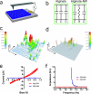
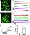
Engineered cardiac patches for treating damaged heart tissues after a heart attack are normally produced by seeding heart cells within three-dimensional porous biomaterial scaffolds. These biomaterials, which are usually made of either biological polymers such as alginate or synthetic polymers such as poly(lactic acid) (PLA), help cells organize into functioning tissues, but poor conductivity of these materials limits the ability of the patch to contract strongly as a unit. Here, we show that incorporating gold nanowires within alginate scaffolds can bridge the electrically resistant pore walls of alginate and improve electrical communication between adjacent cardiac cells. Tissues grown on these composite matrices were thicker and better aligned than those grown on pristine alginate and when electrically stimulated, the cells in these tissues contracted synchronously. Furthermore, higher levels of the proteins involved in muscle contraction and electrical coupling are detected in the composite matrices. It is expected that the integration of conducting nanowires within three-dimensional scaffolds may improve the therapeutic value of current cardiac patches.
Figures


Comment in
-
Nanomedicine: Gold nanowires to mend a heart.Nat Nanotechnol. 2011 Nov 4;6(11):692-3. doi: 10.1038/nnano.2011.195. Nat Nanotechnol. 2011. PMID: 22051743 No abstract available.
Similar articles
-
High-aspect-ratio water-dispersed gold nanowires incorporated within gelatin methacrylate hydrogels for constructing cardiac tissues in vitro.J Mater Chem B. 2020 Aug 19;8(32):7213-7224. doi: 10.1039/d0tb00768d. J Mater Chem B. 2020. PMID: 32638823
-
Novel synthesis strategies for natural polymer and composite biomaterials as potential scaffolds for tissue engineering.Philos Trans A Math Phys Eng Sci. 2010 Apr 28;368(1917):1981-97. doi: 10.1098/rsta.2010.0009. Philos Trans A Math Phys Eng Sci. 2010. PMID: 20308112 Free PMC article.
-
Nanomedicine: Gold nanowires to mend a heart.Nat Nanotechnol. 2011 Nov 4;6(11):692-3. doi: 10.1038/nnano.2011.195. Nat Nanotechnol. 2011. PMID: 22051743 No abstract available.
-
Three-dimensional sprayed active biological gels and cells for tissue engineering application.Biomed Mater Eng. 2008;18(4-5):231-5. Biomed Mater Eng. 2008. PMID: 19065027 Review.
-
[Progress of alginate-based biomedical materials].Zhongguo Xiu Fu Chong Jian Wai Ke Za Zhi. 2013 Aug;27(8):1015-20. Zhongguo Xiu Fu Chong Jian Wai Ke Za Zhi. 2013. PMID: 24171362 Review. Chinese.
Cited by
-
The marriage of Xenes and hydrogels: Fundamentals, applications, and outlook.Innovation (Camb). 2022 Sep 22;3(6):100327. doi: 10.1016/j.xinn.2022.100327. eCollection 2022 Nov 8. Innovation (Camb). 2022. PMID: 36263399 Free PMC article. Review.
-
Engineered Gold and Silica Nanoparticle-Incorporated Hydrogel Scaffolds for Human Stem Cell-Derived Cardiac Tissue Engineering.ACS Biomater Sci Eng. 2024 Apr 8;10(4):2351-2366. doi: 10.1021/acsbiomaterials.3c01256. Epub 2024 Feb 7. ACS Biomater Sci Eng. 2024. PMID: 38323834 Free PMC article.
-
Carbon-nanotube-embedded hydrogel sheets for engineering cardiac constructs and bioactuators.ACS Nano. 2013 Mar 26;7(3):2369-80. doi: 10.1021/nn305559j. Epub 2013 Feb 22. ACS Nano. 2013. PMID: 23363247 Free PMC article.
-
Nanotechnology, an alternative with promising prospects and advantages for the treatment of cardiovascular diseases.Int J Nanomedicine. 2018 Nov 9;13:7349-7362. doi: 10.2147/IJN.S179678. eCollection 2018. Int J Nanomedicine. 2018. PMID: 30519019 Free PMC article. Review.
-
Electrically Conductive Materials: Opportunities and Challenges in Tissue Engineering.Biomolecules. 2019 Sep 4;9(9):448. doi: 10.3390/biom9090448. Biomolecules. 2019. PMID: 31487913 Free PMC article. Review.
References
-
- Leor J, et al. Bioengineered cardiac grafts: A new approach to repair the infarcted myocardium? Circulation. 2000;102:III56–61. - PubMed
-
- Zimmermann WH, et al. Engineered heart tissue grafts improve systolic and diastolic function in infarcted rat hearts. Nature Medicine. 2006;12:452–458. - PubMed
-
- Dvir T, Benishti N, Shachar M, Cohen S. A novel perfusion bioreactor providing a homogenous milieu for tissue regeneration. Tissue Engineering. 2006;12:2843–2852. - PubMed
-
- Radisic M, et al. Medium perfusion enables engineering of compact and contractile cardiac tissue. Am J Physiol Heart Circ Physiol. 2004;286:H507–516. - PubMed
Publication types
MeSH terms
Substances
Grants and funding
- U01 HL100408/HL/NHLBI NIH HHS/United States
- F32GM096546/GM/NIGMS NIH HHS/United States
- R01 GM073626-01A1/GM/NIGMS NIH HHS/United States
- R01 DE013023-06A2/DE/NIDCR NIH HHS/United States
- DE13023/DE/NIDCR NIH HHS/United States
- DE016516/DE/NIDCR NIH HHS/United States
- GM073626/GM/NIGMS NIH HHS/United States
- R01 GM073626/GM/NIGMS NIH HHS/United States
- F32 GM096546-01/GM/NIGMS NIH HHS/United States
- F32 GM096546/GM/NIGMS NIH HHS/United States
- R01 DE016516/DE/NIDCR NIH HHS/United States
- R01 DE013023/DE/NIDCR NIH HHS/United States
- R01 DE016516-01/DE/NIDCR NIH HHS/United States
LinkOut - more resources
Full Text Sources
Other Literature Sources

