

Dissolvable films of silk fibroin for ultrathin conformal bio-integrated electronics
- PMID: 20400953
- PMCID: PMC3034223
- DOI: 10.1038/nmat2745
Dissolvable films of silk fibroin for ultrathin conformal bio-integrated electronics
Abstract
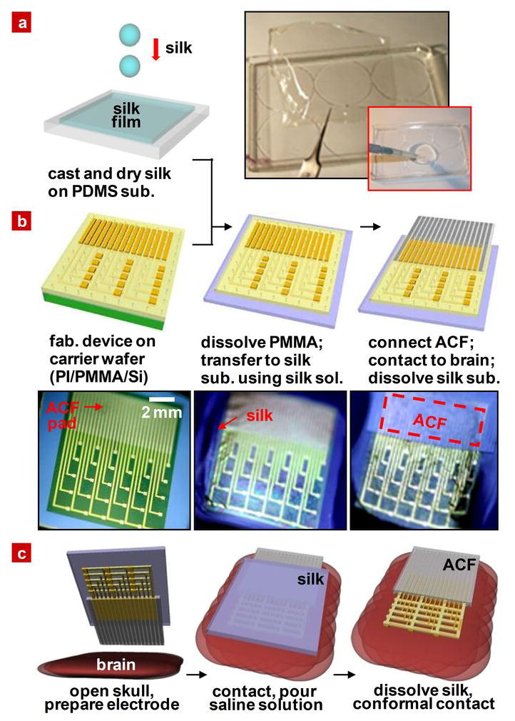
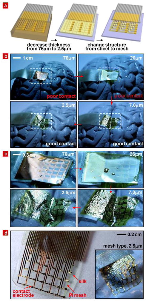
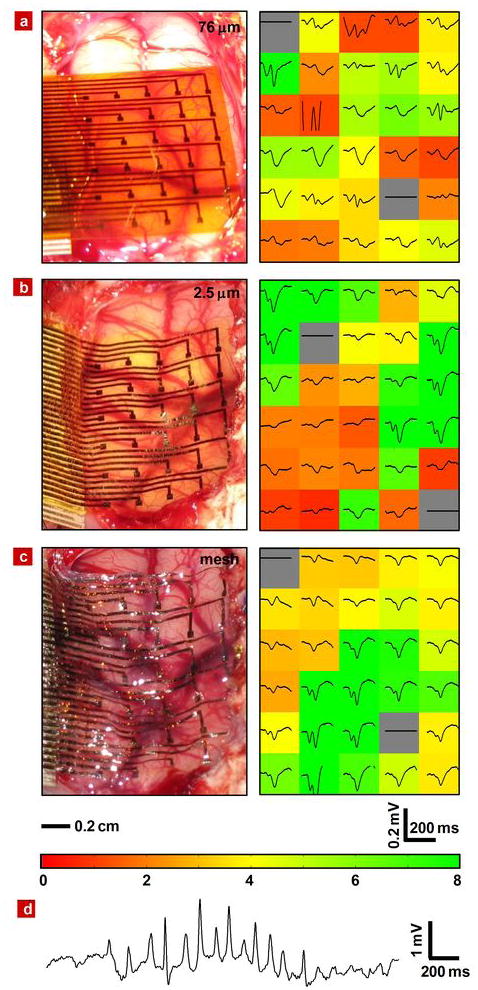
Electronics that are capable of intimate, non-invasive integration with the soft, curvilinear surfaces of biological tissues offer important opportunities for diagnosing and treating disease and for improving brain/machine interfaces. This article describes a material strategy for a type of bio-interfaced system that relies on ultrathin electronics supported by bioresorbable substrates of silk fibroin. Mounting such devices on tissue and then allowing the silk to dissolve and resorb initiates a spontaneous, conformal wrapping process driven by capillary forces at the biotic/abiotic interface. Specialized mesh designs and ultrathin forms for the electronics ensure minimal stresses on the tissue and highly conformal coverage, even for complex curvilinear surfaces, as confirmed by experimental and theoretical studies. In vivo, neural mapping experiments on feline animal models illustrate one mode of use for this class of technology. These concepts provide new capabilities for implantable and surgical devices.
Conflict of interest statement
The authors declare no competing financial interest.
Figures


Similar articles
-
Silk Fibroin for Flexible Electronic Devices.Adv Mater. 2016 Jun;28(22):4250-65. doi: 10.1002/adma.201504276. Epub 2015 Dec 18. Adv Mater. 2016. PMID: 26684370
-
A Stretchable and Transparent Electrode Based on PEGylated Silk Fibroin for In Vivo Dual-Modal Neural-Vascular Activity Probing.Adv Mater. 2021 Aug;33(34):e2100221. doi: 10.1002/adma.202100221. Epub 2021 Jul 18. Adv Mater. 2021. PMID: 34278616
-
Silk-Based Advanced Materials for Soft Electronics.Acc Chem Res. 2019 Oct 15;52(10):2916-2927. doi: 10.1021/acs.accounts.9b00333. Epub 2019 Sep 19. Acc Chem Res. 2019. PMID: 31536330 Review.
-
Degradable Elastomeric Silk Biomaterial for Flexible Bioelectronics.ACS Appl Bio Mater. 2023 Oct 16;6(10):4392-4402. doi: 10.1021/acsabm.3c00593. Epub 2023 Oct 3. ACS Appl Bio Mater. 2023. PMID: 37788457
-
Advancing the frontiers of silk fibroin protein-based materials for futuristic electronics and clinical wound-healing (Invited review).Mater Sci Eng C Mater Biol Appl. 2018 May 1;86:151-172. doi: 10.1016/j.msec.2018.01.007. Epub 2018 Jan 31. Mater Sci Eng C Mater Biol Appl. 2018. PMID: 29525090 Review.
Cited by
-
NeuroGrid: recording action potentials from the surface of the brain.Nat Neurosci. 2015 Feb;18(2):310-5. doi: 10.1038/nn.3905. Epub 2014 Dec 22. Nat Neurosci. 2015. PMID: 25531570 Free PMC article.
-
Materials and fractal designs for 3D multifunctional integumentary membranes with capabilities in cardiac electrotherapy.Adv Mater. 2015 Mar 11;27(10):1731-7. doi: 10.1002/adma.201405017. Epub 2015 Jan 12. Adv Mater. 2015. PMID: 25641076 Free PMC article.
-
Conducting polymer electrodes for auditory brainstem implants.J Mater Chem B. 2015;3(25):5021-5027. doi: 10.1039/c5tb00099h. J Mater Chem B. 2015. PMID: 26207184 Free PMC article.
-
Invited Article: Emerging soft bioelectronics for cardiac health diagnosis and treatment.APL Mater. 2019 Mar 1;7(3):031301. doi: 10.1063/1.5060270. APL Mater. 2019. PMID: 32551188 Free PMC article.
-
Origami-inspired soft fluidic actuation for minimally invasive large-area electrocorticography.Nat Commun. 2024 Jul 26;15(1):6290. doi: 10.1038/s41467-024-50597-2. Nat Commun. 2024. PMID: 39060241 Free PMC article.
References
-
- Kim S, et al. Integrated wireless neural interface based on the Utah electrode array. Biomed Microdevices. 2009;11:453–466. - PubMed
-
- Andersen RA, Musallam S, Pesaran B. Selecting the signals for a brain–machine interface. Current Opinion in Neurobiology. 2004;14:720–726. - PubMed
-
- Mehring C, et al. Inference of hand movements from local field potentials in monkey motor cortex. Nature Neurosci. 2003;6:1253–1254. - PubMed
-
- Ball T, et al. Towards an implantable brain-machine interface based on epicortical field potentials. Biomed Tech. 2004;49:756–759.
Publication types
MeSH terms
Substances
Grants and funding
LinkOut - more resources
Full Text Sources
Other Literature Sources
