. 2008 Aug 8;134(3):474-84.
doi: 10.1016/j.cell.2008.06.024.

Structural basis for cargo regulation of COPII coat assembly

Affiliations

Structural basis for cargo regulation of COPII coat assembly

Scott M Stagg et al. Cell. .

Abstract

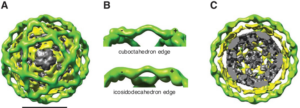
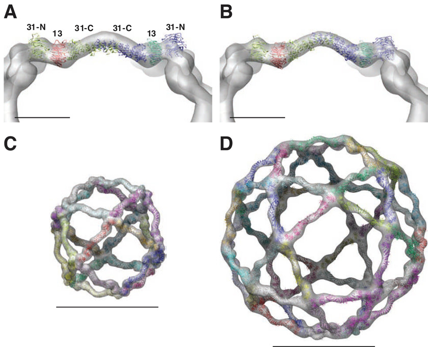
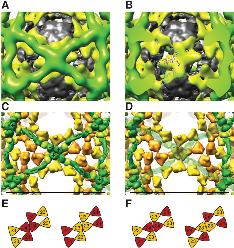
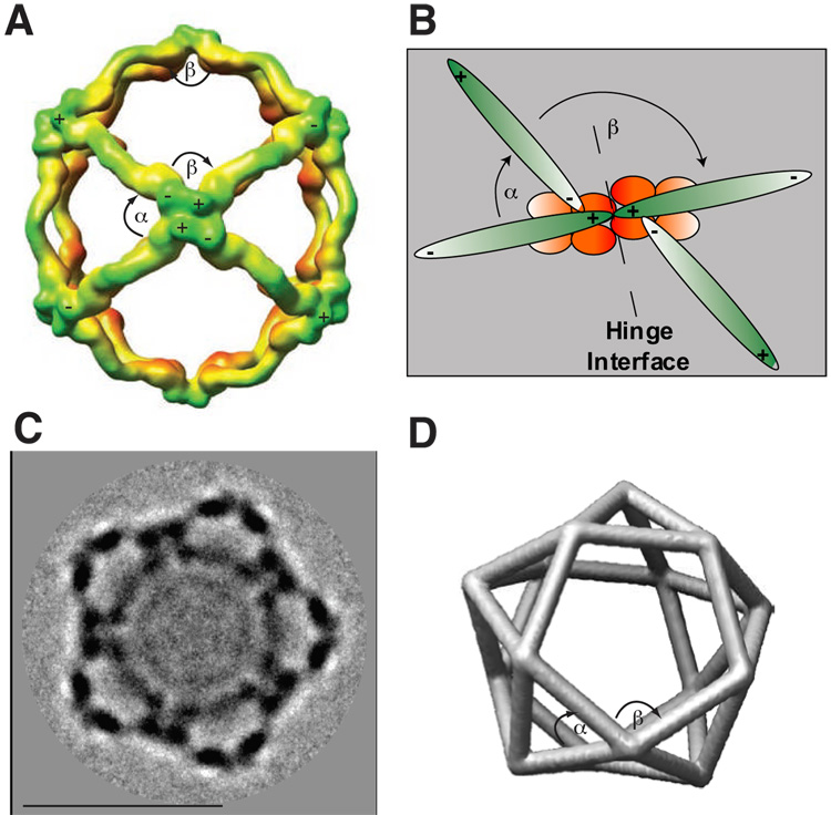
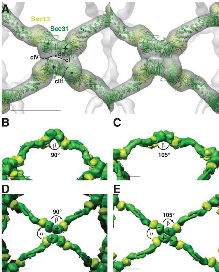
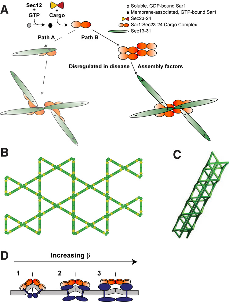
Using cryo-electron microscopy, we have solved the structure of an icosidodecahedral COPII coat involved in cargo export from the endoplasmic reticulum (ER) coassembled from purified cargo adaptor Sec23-24 and Sec13-31 lattice-forming complexes. The coat structure shows a tetrameric assembly of the Sec23-24 adaptor layer that is well positioned beneath the vertices and edges of the Sec13-31 lattice. Fitting the known crystal structures of the COPII proteins into the density map reveals a flexible hinge region stemming from interactions between WD40 beta-propeller domains present in Sec13 and Sec31 at the vertices. The structure shows that the hinge region can direct geometric cage expansion to accommodate a wide range of bulky cargo, including procollagen and chylomicrons, that is sensitive to adaptor function in inherited disease. The COPII coat structure leads us to propose a mechanism by which cargo drives cage assembly and membrane curvature for budding from the ER.


Figures

Fig. 1
Fig. 1
(A) Differential centrifugation COPII assembly assay. COPII proteins Sec13–31 (5µg) and Sec23–24 (3µg) were incubated separately in assembly conditions (1M potassium acetate) for one hour on ice. The samples were then spun at 15,000g for 10 minutes to remove large aggregates; different amounts (marked as percentage) of this pellet are shown in panel A for Sec13–31 and Sec23–24 respectively. The supernatant from this spin was then spun at 200,000g for 20 minutes, this pelleted any cuboctahedron cages that are formed and is shown in the lane marked HSP (high speed pellet). (B) 5µl of a 1.7µM Sec13–31 stock was used for all lanes marked with a +, the volume of Sec23–24 stock (1.2µM) are indicated for each lane. The samples were spun for 10 minutes at 15,000 g (to remove large aggregates – see panel A) and then for 20’ at 200,000 g to pellet cuboctahedrons (shown in (panel C)). Only the high speed pellet fractions were run on the gel shown here. (C) shows a negative stained EM micrograph of Sec13–31 cages and (D) shows an electron micrograph for Sec13–31/Sec23–24 cages. Both (C) and (D) are shown at the same magnification, and the scale bars correspond to 2000Å. (E) Three COPII particles assembled with both Sec13–31 and Sec23–24 observed by cryo-EM. The cages are highlighted by red circles. The scale bar corresponds to 500Å. (F) Reference-free class average of largest cages (the right panel in E), show 5-fold symmetry. (G) Proposed Sec13–31 geometries where four edges combine to form a vertex. From left to right, these are the cuboctahedron, small rhombicuboctahedron, icosidodecahedron, and small rhombicosidodecahedron.
Fig. 2
Fig. 2. Structure of the COPII icosidodecahedron
(A) Single particle reconstruction of the icosidodecahedral cages colored by radius from gray to green. Three layers of EM density are observed corresponding to Sec13–31 (green), Sec23–24 (yellow), and nonspecifically bound proteins (gray). The scale bar corresponds to 500Å. (B) Comparison of the edges of the cuboctahedral cage (top) and icosidodecahedral cage (bottom) shows that their contours are identical. They both show a polarity to the edges so that the ends of the Sec13–31 edges that are closer to the vertex are labeled with a plus (+) and those farther from the vertex are labeled with a minus (−). (C) Slice through the middle of the reconstruction highlighting the three unique layers of density.
Fig. 3
Fig. 3. Atomic models for different COPII cages
(A) Atomic model for the Sec13–31 heterotetramer from Fath et al. (colored ribbons) shown relative to the Sec13–31 cuboctahedron cryo-EM structure (grey). (B) Model for the Sec13–31 heterotetramer fit into the cryo-EM density of a 22 Å resolution cuboctahedron cage. The curve in the center of the edge was modeled by normal modes flexible fitting (coloring as in (A)). (C) Atomic model for the Sec13–31 cuboctahedron (colored ribbons) fit into the cryo-EM density (transparent grey). (D) Atomic model for the icosidodecahedron fit into the cryo-EM density (coloring as in (C)). The scale bars in (A) and (B) correspond to 100 Å while the scale bars in (C) and (D) correspond to 500 Å.
Fig. 4
Fig. 4. Organization of Sec23–24 in the icosidodecahedral cage
(A) View down the two-fold axis of symmetry. (B) Four lobes of density are observed just beneath the vertices. Two Sec23–24 crystal structures (ribbons) fit well in the asymmetric unit, though an unambiguous fit could not be determined. (C) Reduced representation (surface rendering) view of the crystal structures of Sec13–31 and Sec23–24 that have been fit into the icosidodecahedron cryo-EM density in the same orientation as (A). Dark green lobes labeled with plus and minuses are Sec31 WD40 β-propeller domains. The light green lobes adjacent to Sec31 WD40 domains are Sec13 WD40 β-propeller containing structures. (D) The same view as (C) but with the Sec13–31 vertex made transparent. This shows that the crystal structure of Sec23–24 has the same general shape and features as the EM density (B). (E) Two possible parallel orientations for Sec23–24. Red triangles correspond to Sec23 and orange triangles correspond to Sec24. (F) Two possible antiparallel orientations for Sec23–24. Coloring is the same as in (E). The scale bars in (A – D) correspond to 500 Å.
Fig. 5
Fig. 5. Angles influencing the structure of the COPII cage
(A) The cuboctahedral cage with α and β angles labeled. Sec13–31 is off-center with respect to the geometric edge, giving the structure polarity. As in figure 2, the ends of the Sec13–31 edges containing the Sec31 WD40 β-propeller motifs that are closer to the vertex are labeled with a plus (+) and those farther from the vertex are labeled with a minus (−). α is the angle between the plus end of an edge and the adjacent edge in the clockwise direction. Likewise, β is the angle between the minus end of an edge and the adjacent edge in the clockwise direction. (B) A diagram of the different Sec13–31 edges linked at the vertex to form the fixed α and variable β angles in relationship to the underlying Sec23–24 tetramer cluster observed in the structure (Fig. 5). It should be noted that because the faces derived from the α and β angles do not lie in the same plane, their sum does not equal 360° until a planar conformation is achieved (i.e. β angle of 120°). A possible hinge interface for the tetramer cluster is indicated by a dashed line. (C) Reference-free class average of pentagonal-shaped intermediate-sized particles shown in Fig. 2B, middle panel. The scale bar corresponds to 500 Å. (D) Model of the D5 coat based on class average in C.
Fig. 6
Fig. 6. Mechanism for the expansion of the COPII cage from the cuboctahedron to the icosidodecahedron
(A) Stereo view of the vertex of the cuboctahedron with the atomic model of Sec13–31 fit into the cryo-EM density (transparent grey). Sec13 WD40 β-propeller domain is represented by light green ribbons while Sec31 is represented by dark green ribbons with the WD40 β-propeller domain labeled with pluses and minuses. The putative contacts mediating the formation of the vertex are indicated by cI-cIV. These contacts all appear to be facilitated through the WD40 β-propeller containing domains. Contacts I and III appear to rotate relative to each other when transitioning from a cuboctahedron to an icosidodecahedron (B–E). (B) Reduced representation (surface rendering) depiction of the side view of the Sec13–31 cuboctahedron vertex. Colors are the same as (A). α and β angles are indicated. (C) Side view of the Sec13–31 icosidodecahedron vertex. (D) Top view of the cuboctahedron vertex. (E) Top view of the icosidodecahedron vertex. See Supplemental Movie S5 for animation of changes in the vertex hinge region during transition from the cuboctahedron to the icosidodecahedron. The scale bars in (A – E) correspond to 100 Å.
Fig. 7
Fig. 7. Models for COPII coat formation and expanded COPII structures
(A) A scheme of sequential COPII protein recruitment to the ER membrane. In path A, Sar1 activation results in recruitment of Sec23–24 (which binds protein cargo) and, according to current models, Sec13–31. This sequence predicts the congruous Sec23–24 arrangement shown at the end of path A, a result that is not observed in the COPII coat structure. Path B shows how Sec23-24 oligomerization prior to and independent of Sec13-31 recruitment could result in the observed arrangement of Sec23–24 in the COPII coat structure and define the physical properties of the vertex. The possible role of assembly factors in combination with Sec23–24 in facilitating tetramer cluster organization at exit sites is indicated. (B) Ạ possiblẹ planạr structurẹ of̣ Sec13–31 if̣ β can form angles up to 120°. Sec13 is represented as light green circles and Sec31 is represented in dark green. (C) A hypothetical tubular structure of Sec13–31. (D) A side view of the Sec23–24 tetramer cluster showing the effect of increasing cargo size on the hinge region (dashed lines). Increasing cargo size would result in Sec23–24 tetramer cluster configurations that would increase the resultant β angle generated by Sec13–31 recruitment.

Comment in

Similar articles

Cited by

References

    1. Antonny B, Bigay J, Casella JF, Drin G, Mesmin B, Gounon P. Membrane curvature and the control of GTP hydrolysis in Arf1 during COPI vesicle formation. Biochem Soc Trans. 2005;33:619–622. - PubMed
    1. Antonny B, Gounon P, Schekman R, Orci L. Self-assembly of minimal COPII cages. EMBO Rep. 2003;4:419–424. - PMC - PubMed
    1. Aridor M, Bannykh SI, Rowe T, Balch WE. Cargo can modulate COPII vesicle formation from the endoplasmic reticulum. J Biol Chem. 1999;274:4389–4399. - PubMed
    1. Aridor M, Fish KN, Bannykh S, Weissman J, Roberts TH, Lippincott-Schwartz J, Balch WE. The Sar1 GTPase coordinates biosynthetic cargo selection with endoplasmic reticulum export site assembly. J Cell Biol. 2001;152:213–229. - PMC - PubMed
    1. Aridor M, Weissman J, Bannykh S, Nuoffer C, Balch WE. Cargo selection by the COPII budding machinery during export from the ER. J Cell Biol. 1998;141:61–70. - PMC - PubMed

Publication types

MeSH terms