. 2007 Mar 15;53(6):789-803.
doi: 10.1016/j.neuron.2007.02.018.

In vivo simultaneous tracing and Ca(2+) imaging of local neuronal circuits

Affiliations

In vivo simultaneous tracing and Ca(2+) imaging of local neuronal circuits

Shin Nagayama et al. Neuron. .

Abstract

A central question about the brain is how information is processed by large populations of neurons embedded in intricate local networks. Answering this question requires not only monitoring functional dynamics of many neurons simultaneously, but also interpreting such activity patterns in the context of neuronal circuitry. Here, we introduce a versatile approach for loading Ca(2+) indicators in vivo by local electroporation. With this method, Ca(2+) imaging can be performed both at neuron population level and with exquisite subcellular resolution down to dendritic spines and axon boutons. This enabled mitral cell odor-evoked ensemble activity to be analyzed simultaneously with revealing their specific connectivity to different glomeruli. Colabeling of Purkinje cell dendrites and intersecting parallel fibers allowed Ca(2+) imaging of both presynaptic boutons and postsynaptic dendrites. This approach thus provides an unprecedented capability for in vivo visualizing active cell ensembles and tracing their underlying local neuronal circuits.


Figures
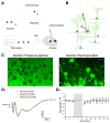
Figure 1
Figure 1
Equipment setup, dye loading mechanism and evaluating disruptive effect of electroporation on network function. A, Schematic diagram showing the experimental setup. An electric circuit, consisting of a pulse generator, a current-output isolator, a series resistor, a Ca2+ dye-filled glass pipette, an anesthetized animal and a metal clip attached to the mouse tail, was used for local electroporation. The waveform and amplitude of current pulses were monitored on an oscilloscope by measuring the voltage drop across a 100-KΩ resistor. B, Schematic illustration of how Ca2+ indicators are loaded to visualize local neuronal circuits. Cell membrane in close vicinity of the pipette tip was transiently ruptured by electric current pulses, and Ca2+ dyes were electrophoresed into the axons and dendrites that passed through a small effective dye-loading area. The loaded dyes were then transported or simply diffused along axons and dendrites to visualize the entire-neuron morphology. C, Evidence for the critical involvement of membrane electroporation in dextran dye labeling. Left panel, loading dextran dye into the barrel cortex simply by pressure ejection (6 psi, 5 sec) did not lead to successful neuronal labeling. Right panel, loading the same dextran-dye solution by electroporation led to the labeling of many neurons with both soma and processes visualized. The two images were taken at three hours after loading with 10% dextran-conjugated Calcium Green-1 (CG-1). Scale bar, 10 μm. D1, Local field potentials recorded in the olfactory bulb external plexiform layer before and after electroporation. Field potentials were evoked by electric stimulation of the lateral olfactory tract. The first negative peak at 1–3 ms after the stimulus onset (arrow) indicates the antidromic activation of mitral cells, while the second and third peaks reflect the functional activation of local synaptic circuits. Three different field-potential traces are superimposed for comparison, which are average of the recordings made, respectively, at 0–10 min before and 0–10 or 20–30 min after electroporation. D2, Plotting over time the normalized amplitude of the second negative peak before and after electroporation. The shaded area indicates 10-min electroporation. Field potentials were first normalized as percentage of the mean baseline amplitude before electroporation, and were then averaged across different experiments. Each data point is presented as mean±SEM.
Figure 2
Figure 2
Effects of different parameters on dextran-dye loading efficiency and an estimate of intracellular Ca2+ dye concentration. A, B and C, Plots of the total number of labeled neurons per electroporation in the barrel cortex with the current pulse amplitude (A), current pulse duration (B) and dextran-conjugated CG-1 (10,000 m.w.) concentration (C). For A, the other two loading parameters were 25 ms current pulse width and 10% dextran CG-1; for B, the parameters were 3 μA current and 10% dextran; and for C, 3 μA current amplitude and 25 ms pulse duration. All the loading pipettes had a tip inner diameter of ~2.5 μm, and a total of 1200 pulses were delivered at 2 Hz. In A and B, black bars indicate the percentage of incidence in which the loading pipette got clogged during electroporation. The clogging of pipette usually happened at a large current amplitude (10 μA for 25 ms pulses) or with a long pulse duration (200 ms for 3 μA current). D, Histogram showing the distribution of estimated CG-1 concentration in 45 neurons labeled by local electroporation with parameters of 3 μA current, 25 ms pulse duration, 1200 pulses at 2 Hz and 10% CG-1 dextran conjugate (10,000 m.w.).
Figure 3
Figure 3
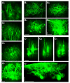
In vivo two-photon imaging of neuronal labeling with dextran-conjugated Ca2+ indicators in three representative brain regions. A, olfactory bulb; B, barrel cortex; C, cerebellum. A1, A2 and A3 are fluorescence images obtained by projecting in z-axis the images captured consecutively from three different ranges of depth (0–125, 125–250 and 250–400 μm). A4 is a side projection of the entire image stack from A1, A2 and A3. B1, B2 and B3 are three images obtained by z-projection for a depth range of 0–100, 100–200 and 200–300 μm, respectively. B4 is a side projection of the entire image stack from B1, B2 and B3. C1, C2 and C3 are compressed from images taken at the depth of 0–100, 100–150 and 150–250 μm. C4 is a side view reconstructed from a different image stack. Three video files (Movies A, B, C) are provided in Supplemental Materials to give a better 3-D illustration of labeling in these different brain regions. Scale bars, 50 μm. A4, B4 and C4 are horizontally stretched and thus carry two different scale bars.
Figure 4
Figure 4
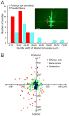
Small restricted dye-loading area and broad distribution of labeled neurons. A, Quantifying the labeled bundle widths of both parallel fibers and Purkinje cell dendrites in the cerebellum. Red columns show the width distribution of labeled parallel fibers, and cyan columns are distribution of labeled Purkinje cell dendrites. The inset shows an example of labeling obtained by z-projection of an image stack. The loading conditions were 5% dextran-bound OGB-1 (10,000 m.w.), 2 μA current, 100 ms pulse width and 900 pulses delivered at 5 Hz. Please note that in this case only one Purkinje cell was labeled, with its soma indicated by a white arrow. The vertical fluorescent bundle is Purkinje cell dendrites, and the horizontal bundle is labeled parallel fibers. Also indicated is how the widths of labeling were measured. Scale bar, 50 μm. B, Summary of the distribution patterns of labeled neuronal somas in three brain regions. The dye injection sites are aligned at the center of the diagram. Blue triangles indicate the distribution of labeled cells in the cerebellum, green diamonds reflect labeling in the barrel cortex, and red squares are labeling in the olfactory bulb. The vertical and horizontal axes correspond, respectively, to the rostro-caudal and medio-lateral directions.
Figure 5
Figure 5
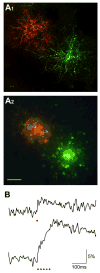
Electroporation using regular salt-form Ca2+ dyes. A, In vivo two-photon imaging of the barrel-cortex neurons labeled by two separate electroporations using 5% CG-1 hexapotasssium and 5% X-rhod-1 tripotassium, respectively. The loading parameters were both -3 μA current amplitude, 25 ms pulse duration and 1200 pulses delivered at 2 Hz. A1 shows the z-projection of labeled dendrites imaged at a depth range of 50 to 115 μm below the pia. A2 is the z-projection of images between 185 and 250 μm, showing the labeled cell bodies. Scale bar, 50 μm. B, Ca2+ responses of a neuron labeled with CG-1 hexapotassium salt. The two traces show the responses to one (upper) and five (lower) electric stimuli as indicated by red dots. For each trace, five imaging trials were averaged.
Figure 6
Figure 6
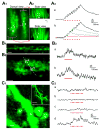
Local electric stimulation-evoked Ca2+ responses in different subcellular structures. A, Ca2+ response in Purkinje cell dendrites. A1, A top view of labeled distal dendritic arbors. The dashed line indicates the location where line-scan two-photon imaging was performed. A2, Upper and lower panels show the side views of two labeled Purkinje-cell distal dendritic arbor arrays. Their correspondence to the top-view image in A1 is indicated by two white circles (a, b), where Ca2+ responses shown in A3 were measured. A3, Upper trace is a dendritic Ca2+ response evoked at site a by ten electric pulses delivered laterally to unlabeled parallel fibers. Bottom traces are superimposed responses at site b to 2, 4, 6, and 10 stimuli. Ten trials were averaged for each trace. B, Imaging Ca2+ activity in vivo in parallel-fiber presynaptic boutons. B1, A representative fluorescence image showing presynaptic boutons along the parallel fibers. For better visualization see Supplemental Movie E. B2, Line-scan imaging was performed, with Ca2+ responses in boutons a and b shown in B3. B3, Responses of boutons a and b to ten electric pulses applied laterally to the labeled parallel fibers. Ten trials were averaged for each trace. C, In vivo Ca2+ imaging of pyramidal cell dendritic spines in the barrel cortex. C1, Two-photon images showing a pyramidal cell apical dendrite covered with many spines. The inset in the up-right corner is a low-magnification image, in which a white square box indicates the area that was zoomed in for Ca2+ imaging. Line-scan recording was made along a dashed line which covered three spines (a, c, d) and their parental dendrite (b). C2, Only one out of three spines showed a Ca2+ response to ten electric stimuli. No Ca2+ increase was observed in the parental dendritic shaft. Eight trials were averaged for each trace. Red dots below the traces in A3, B3 and C2 indicate individual electric stimuli. Scale bars represent 5 μm in A1, A2, B1, B2 and in the inset of C1, but 1 μm in the major image of C1.
Figure 7
Figure 7
Imaging odor-evoked Ca2+ response along the mitral cell soma-primary dendrite axis. A, A labeled mitral cell with its soma, primary dendrite trunk and glomerular tuft branches visualized within the same imaging plane. Ca2+ responses were analyzed respectively in the glomerular tuft branches, the distal and proximal primary dendrite trunk, and the soma. Scale bar, 25 μm. B, Odor-evoked Ca2+ increase was imaged at 2 Hz in frame-scan mode and subsequently measured in the four subcellular compartments as indicated in A. Aliphatic aldehydes with different carbon-chain length were delivered to activate olfactory sensory input. In each vertical column are Ca2+ responses in the different compartments to the same aldehyde stimulus, and each row shows the responses to different aldehydes within a certain compartment. Red bars under each trace indicate the timing of odor delivery.
Figure 8
Figure 8
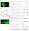
Ca2+ imaging of multiple neurons for monitoring cell ensemble activity in a natural sensory process. A, Two labeled neurons in the barrel cortex were line-scan imaged to reveal their Ca2+ activity in response to whisker stimulation. A1, An imaged area in the barrel cortex that was located 260 μm below the pia. Scale bar, 10 μm. A2, The two neurons indicated in A1 displayed a Ca2+ increase to whisker deflection. Red bars indicate the timing of an air puff. B, Imaging odor responses of 10 mitral cells in the olfactory bulb. B1, The relative locations of ten mitral cells within the same focus plane. The dendritic projection of these neurons is illustrated partially in a lower-magnification image shown in Figure 3A. Scale bar, 25 μm. B2, Simultaneous Ca2+ recording from the ten mitral cells designated as a to j in B1. Each column represents the responses of ten different mitral cells to a given aldehyde, and each row shows the responses of a certain mitral cell to the six different aldehydes. Red bars indicate the timing of odor delivery, and Ca2+ imaging was carried out in frame-scan mode at 2 Hz.

Comment in

Similar articles

Cited by

References

    1. Beierlein M, Gee KR, Martin VV, Regehr WG. Presynaptic calcium measurements at physiological temperatures using a new class of dextran-conjugated indicators. J Neurophysiol. 2004;92:591–599. - PubMed
    1. Bonnot A, Mentis GZ, Skoch J, O’Donovan MJ. Electroporation loading of calcium-sensitive dyes into the CNS. J Neurophysiol. 2005;93:1793–1808. - PubMed
    1. Bozza T, McGann JP, Mombaerts P, Wachowiak M. In vivo imaging of neuronal activity by targeted expression of a genetically encoded probe in the mouse. Neuron. 2004;42:9–21. - PubMed
    1. Brecht M, Roth A, Sakmann B. Dynamic receptive fields of reconstructed pyramidal cells in layers 3 and 2 of rat somatosensory barrel cortex. J Physiol. 2003;553:243–265. - PMC - PubMed
    1. Charpak S, Mertz J, Beaurepaire E, Moreaux L, Delaney K. Odor-evoked calcium signals in dendrites of rat mitral cells. Proc Natl Acad Sci U S A. 2001;98:1230–1234. - PMC - PubMed

Publication types