Voltage-dependent hydration and conduction properties of the hydrophobic pore of the mechanosensitive channel of small conductance
- PMID: 16500980
- PMCID: PMC1440736
- DOI: 10.1529/biophysj.105.080432
Voltage-dependent hydration and conduction properties of the hydrophobic pore of the mechanosensitive channel of small conductance
Abstract
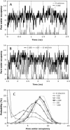
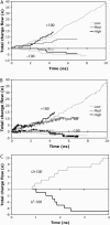
A detailed picture of water and ion properties in small pores is important for understanding the behavior of biological ion channels. Several recent modeling studies have shown that small, hydrophobic pores exclude water and ions even if they are physically large enough to accommodate them, a mechanism called hydrophobic gating. This mechanism has been implicated in the gating of several channels, including the mechanosensitive channel of small conductance (MscS). Although the pore in the crystal structure of MscS is wide and was initially hypothesized to be open, it is lined by hydrophobic residues and may represent a nonconducting state. Molecular dynamics simulations were performed on MscS to determine whether or not the structure can conduct ions. Unlike previous simulations of hydrophobic nanopores, electric fields were applied to this system to model the transmembrane potential, which proved to be important. Although simulations without a potential resulted in a dehydrated, occluded pore, the application of a potential increased the hydration of the pore and resulted in current flow through the channel. The calculated channel conductance was in good agreement with experiment. Therefore, it is likely that the MscS crystal structure is closer to a conducting than a nonconducting state.
Figures


Similar articles
-
Mechanosensitive channel MscS in the open state: modeling of the transition, explicit simulations, and experimental measurements of conductance.J Gen Physiol. 2008 Jul;132(1):67-83. doi: 10.1085/jgp.200810000. J Gen Physiol. 2008. PMID: 18591417 Free PMC article.
-
Electrostatic properties of the mechanosensitive channel of small conductance MscS.Biophys J. 2006 May 15;90(10):3496-510. doi: 10.1529/biophysj.105.080069. Epub 2006 Mar 2. Biophys J. 2006. PMID: 16513774 Free PMC article.
-
Water dynamics and dewetting transitions in the small mechanosensitive channel MscS.Biophys J. 2004 May;86(5):2883-95. doi: 10.1016/S0006-3495(04)74340-4. Biophys J. 2004. PMID: 15111405 Free PMC article.
-
Molecular simulation studies of hydrophobic gating in nanopores and ion channels.Biochem Soc Trans. 2015 Apr;43(2):146-50. doi: 10.1042/BST20140256. Biochem Soc Trans. 2015. PMID: 25849908 Review.
-
Hydrophobic dewetting in gating and regulation of transmembrane protein ion channels.J Chem Phys. 2020 Sep 21;153(11):110901. doi: 10.1063/5.0017537. J Chem Phys. 2020. PMID: 32962356 Free PMC article. Review.
Cited by
-
Interaction between the cytoplasmic and transmembrane domains of the mechanosensitive channel MscS.Biophys J. 2008 Mar 1;94(5):1638-45. doi: 10.1529/biophysj.107.114785. Epub 2007 Nov 9. Biophys J. 2008. PMID: 17993482 Free PMC article.
-
Computational study of the transmembrane domain of the acetylcholine receptor.Eur Biophys J. 2009 Sep;38(7):961-70. doi: 10.1007/s00249-009-0476-3. Epub 2009 May 23. Eur Biophys J. 2009. PMID: 19466401
-
A structural mechanism for MscS gating in lipid bilayers.Science. 2008 Aug 29;321(5893):1210-4. doi: 10.1126/science.1159674. Science. 2008. PMID: 18755978 Free PMC article.
-
A structural model for facultative anion channels in an oligomeric membrane protein: the yeast TRK (K(+)) system.Pflugers Arch. 2015 Dec;467(12):2447-60. doi: 10.1007/s00424-015-1712-6. Epub 2015 Jun 24. Pflugers Arch. 2015. PMID: 26100673
-
Mechanosensitive channels: insights from continuum-based simulations.Cell Biochem Biophys. 2008;52(1):1-18. doi: 10.1007/s12013-008-9024-5. Epub 2008 Sep 12. Cell Biochem Biophys. 2008. PMID: 18787764 Free PMC article. Review.
References
-
- Hille, B. 2001. Ion Channels of Excitable Membranes, 3rd ed. Sinauer Associates, Sunderland, MA.
-
- Zhou, Y., J. H. Morais-Cabral, A. Kaufman, and R. MacKinnon. 2001. Chemistry of ion coordination and hydration revealed by a K+ channel-Fab complex at 2.0 Å resolution. Nature. 414:43–48. - PubMed
-
- Betanzos, M., C. S. Chiang, H. R. Guy, and S. Sukharev. 2002. A large iris-like expansion of a mechanosensitive channel protein induced by membrane tension. Nat. Struct. Biol. 9:704–710. - PubMed
-
- Song, L., M. R. Hobaugh, C. Shustak, S. Cheley, H. Bayley, and J. E. Gouaux. 1996. Structure of staphylococcal alpha-hemolysin, a heptameric transmembrane pore. Science. 274:1859–1866. - PubMed
Publication types
MeSH terms
Substances
Grants and funding
LinkOut - more resources
Full Text Sources
Other Literature Sources
Molecular Biology Databases

