. 1999 Nov;10(11):3745-69.
doi: 10.1091/mbc.10.11.3745.

Keratocytes generate traction forces in two phases

Affiliations
Free PMC article

Keratocytes generate traction forces in two phases

K Burton et al. Mol Biol Cell. 1999 Nov.
Free PMC article

Abstract

Forces generated by goldfish keratocytes and Swiss 3T3 fibroblasts have been measured with nanonewton precision and submicrometer spatial resolution. Differential interference contrast microscopy was used to visualize deformations produced by traction forces in elastic substrata, and interference reflection microscopy revealed sites of cell-substratum adhesions. Force ranged from a few nanonewtons at submicrometer spots under the lamellipodium to several hundred nanonewtons under the cell body. As cells moved forward, centripetal forces were applied by lamellipodia at sites that remained stationary on the substratum. Force increased and abruptly became lateral at the boundary of the lamellipodium and the cell body. When the cell retracted at its posterior margin, cell-substratum contact area decreased more rapidly than force, so that stress (force divided by area) increased as the cell pulled away. An increase in lateral force was associated with widening of the cell body. These mechanical data suggest an integrated, two-phase mechanism of cell motility: (1) low forces in the lamellipodium are applied in the direction of cortical flow and cause the cell body to be pulled forward; and (2) a component of force at the flanks pulls the rear margins forward toward the advancing cell body, whereas a large lateral component contributes to detachment of adhesions without greatly perturbing forward movement.


Figures
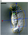
Figure 1
Figure 1
Image analysis. (A) Whole cells and features of interest in time-lapse sequences were tracked to quantitate position and orientation. Features were tracked with the use of numbered graphical objects: short bars with a dot in the middle were positioned at the center of compression wrinkles and oriented in the direction of force (orthogonal to the wrinkle); circles indicate the positions of small features such as organelles or small distortions in the elastic substratum. The positions and orientations of cells were tracked with MacWrinkle software to place a grid on the image or with MacDraw Pro and NIH Image to outline the cell (see MATERIALS AND METHODS). Movements are shown by trajectories drawn on the image. The grid and a long bar show the MacWrinkle and NIH Image estimates of location (near the front of the cell body in this image) and orientation, respectively. These estimates were similar, although the absolute centroids were offset. (B) Cell orientation (grid, triangles; outline, squares) versus time. The upper horizontal axis shows time point (128 images over 47 s). Cell orientation was calculated from the orientation of the grid (MacWrinkle) or from an ellipse fitted to the cell outline (NIH Image). The data in A and B were taken from the same image sequence as the data in Figure 2, A, D, and E. Bar, 10 μm.
Figure 1
Figure 1
Image analysis. (A) Whole cells and features of interest in time-lapse sequences were tracked to quantitate position and orientation. Features were tracked with the use of numbered graphical objects: short bars with a dot in the middle were positioned at the center of compression wrinkles and oriented in the direction of force (orthogonal to the wrinkle); circles indicate the positions of small features such as organelles or small distortions in the elastic substratum. The positions and orientations of cells were tracked with MacWrinkle software to place a grid on the image or with MacDraw Pro and NIH Image to outline the cell (see MATERIALS AND METHODS). Movements are shown by trajectories drawn on the image. The grid and a long bar show the MacWrinkle and NIH Image estimates of location (near the front of the cell body in this image) and orientation, respectively. These estimates were similar, although the absolute centroids were offset. (B) Cell orientation (grid, triangles; outline, squares) versus time. The upper horizontal axis shows time point (128 images over 47 s). Cell orientation was calculated from the orientation of the grid (MacWrinkle) or from an ellipse fitted to the cell outline (NIH Image). The data in A and B were taken from the same image sequence as the data in Figure 2, A, D, and E. Bar, 10 μm.
Figure 2
Figure 2
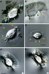
Traction force increases at discrete locations on the substratum. DIC (A, D, and E) and IRM (C, F, and G) images of the same keratocyte locomoting on a stiff substratum. Panels D and E and panels F and G show sequences of the left and right flanks from the full images in A and C, respectively. (B) A cell in which the left flank was stretched into a tail after the cell turned and moved slowly to the right. The cell in B was located just above that in C and F, and the wrinkle at the end of its tail, outlined in B and C, is also visible in F. Each image in A–G is the average of five video frames (0.165 s). The contrast in each image (A–C) or sequence (D–G) was independently adjusted in software to enhance the visibility of the features of interest. Numbers in A–C and E–G (center of each row) refer to time (seconds) elapsed since the cell was at the start of the respective trajectory shown in A and C. The IRM data were acquired 2 min and 10 s after the DIC data. A small vertical bar at the front of the cell body in A and C indicates the location and orientation of the reference used to track the cell’s trajectory (see Figure 1). The trajectories are marked at 3.7-s intervals. Arrowheads indicate the positions and directions of traction forces that produced curved wrinkles. In the DIC images (A, D, and E), force was directed 5–25 degrees forward of the lateral axis of the cell, indicating that the forward component of traction force was 10–40% of the total (see H below). Within measurement accuracy, wrinkles were stationary with respect to the field of view; the small lines on wrinkles 1 and 2 in A show that their displacement was much less than the cell’s movement during the same period (numbered markers on the trajectory in A). The close contact indicated by the arrow at the right front lamellipodium in G also moved only slightly (<0.5 μm, shown by a dot on the contact outlined at the asterisk in C), whereas the cell moved greatly (∼5 μm, shown by two asterisks on the cell trajectory; the average cell velocity before retraction was 20–30 μm/min). Two additional close contacts near the midline of the lamellipodium (at 16.9 and 43.3–46.6 s [data not shown]) also exhibited no measurable displacement. When the close contact at the left flank lifted up and retracted (note the bright region at the left flank in front of the wrinkle at 30.1 s), it changed shape so that it appeared to move (in C, the trajectory within the circle at the left flank shows the movement of the close contact during the period when the cell moved between the circles on its trajectory). In contrast, for the slowly moving tethered cell in B, close contacts made by the lamellipodium (arrow) showed rapid retrograde movement over the substratum (see text). Bar, 18 μm. (H) Traction force versus time for wrinkles 1–3 in A, D, and E. (I) Force, stress, and contact area at the retracting left flank in the IRM images (C, F, and G). Force was calculated from wrinkle length, and stress was calculated by dividing force by the area of close contact behind the wrinkle visible in the IRM image.
Figure 2
Figure 2
Traction force increases at discrete locations on the substratum. DIC (A, D, and E) and IRM (C, F, and G) images of the same keratocyte locomoting on a stiff substratum. Panels D and E and panels F and G show sequences of the left and right flanks from the full images in A and C, respectively. (B) A cell in which the left flank was stretched into a tail after the cell turned and moved slowly to the right. The cell in B was located just above that in C and F, and the wrinkle at the end of its tail, outlined in B and C, is also visible in F. Each image in A–G is the average of five video frames (0.165 s). The contrast in each image (A–C) or sequence (D–G) was independently adjusted in software to enhance the visibility of the features of interest. Numbers in A–C and E–G (center of each row) refer to time (seconds) elapsed since the cell was at the start of the respective trajectory shown in A and C. The IRM data were acquired 2 min and 10 s after the DIC data. A small vertical bar at the front of the cell body in A and C indicates the location and orientation of the reference used to track the cell’s trajectory (see Figure 1). The trajectories are marked at 3.7-s intervals. Arrowheads indicate the positions and directions of traction forces that produced curved wrinkles. In the DIC images (A, D, and E), force was directed 5–25 degrees forward of the lateral axis of the cell, indicating that the forward component of traction force was 10–40% of the total (see H below). Within measurement accuracy, wrinkles were stationary with respect to the field of view; the small lines on wrinkles 1 and 2 in A show that their displacement was much less than the cell’s movement during the same period (numbered markers on the trajectory in A). The close contact indicated by the arrow at the right front lamellipodium in G also moved only slightly (<0.5 μm, shown by a dot on the contact outlined at the asterisk in C), whereas the cell moved greatly (∼5 μm, shown by two asterisks on the cell trajectory; the average cell velocity before retraction was 20–30 μm/min). Two additional close contacts near the midline of the lamellipodium (at 16.9 and 43.3–46.6 s [data not shown]) also exhibited no measurable displacement. When the close contact at the left flank lifted up and retracted (note the bright region at the left flank in front of the wrinkle at 30.1 s), it changed shape so that it appeared to move (in C, the trajectory within the circle at the left flank shows the movement of the close contact during the period when the cell moved between the circles on its trajectory). In contrast, for the slowly moving tethered cell in B, close contacts made by the lamellipodium (arrow) showed rapid retrograde movement over the substratum (see text). Bar, 18 μm. (H) Traction force versus time for wrinkles 1–3 in A, D, and E. (I) Force, stress, and contact area at the retracting left flank in the IRM images (C, F, and G). Force was calculated from wrinkle length, and stress was calculated by dividing force by the area of close contact behind the wrinkle visible in the IRM image.
Figure 4
Figure 4
Cell body widening is associated with increased traction force. A cell that initially moved rapidly (A) with a flat lamellipodium and rounded cell body but then slowed (B) as it generated curved wrinkles at its flanks (force = 235 nN for the wrinkle traced at the left flank), force spots under the anterior lamellipodium (circles), and small wrinkles that extended from force spots (ovals and arrowheads). The cell body widened (double-headed arrow is the same length in A and B), and organelles (arrows) moved laterally when force increased (B). Time is shown in seconds. Bar, 10 μm.
Figure 5
Figure 5
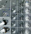
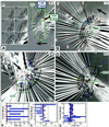
Traction forces are applied across the entire cell. (A) A large keratocyte that generated high forces on a stiff substratum (wrinkle traced at cell’s right corresponds to 680 nN). Wrinkles were produced at the flanks (arrows) and across the entire cell body (arrowheads). Most wrinkles were located along the boundary of the lamellipodium and the cell body, and the pattern was symmetrical about the midline of the cell. The box at 0 s is magnified in the lower four panels (3–12 s). The cross hair marks the position of the origin of a tension wrinkle, with the direction of force indicated by the arrowhead. The dashed line and the cross hair are at the same position in the field of view in each image, showing very little displacement of the origin of the wrinkle. Numbers indicate seconds. Bars, 5 μm. (B–D) A cell observed in DIC (B and C) and IRM (D). (B) Single arrowheads at 0 s indicate the location and orientation of traction forces producing curved compression wrinkles. The traced wrinkle at the left side of the midline at 60 s corresponds to 600 nN, whereas the force at the right flank was 70 nN. Boxed areas are magnified in C, and intermediate time points are shown. Paired arrowheads in B bracket a constant location in the field of view where a wrinkle was tracked as the cell passed over, shown by cross hairs in C. The arrows in C indicate the direction of force, which rotated by ∼90 degrees as the front of the cell body passed over (see text). (D) Sequence demonstrating the continued presence of central wrinkles when the right flank retracted (arrowheads). The direction of force near the midline reversed as the center of the cell shifted to the left (arrows at 32 and 48 s). Bars, 5 μm.
Figure 6
Figure 6
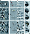
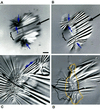
Deformation of highly compliant substrata. (A and B) DIC and IRM images of one keratocyte on a highly compliant substratum. Outlined areas under the cell body show where the silicone rubber was crinkled, obscuring wrinkles that were otherwise present (compare times 6 min and 7 min 28 s in B). Wrinkles were out of focus under the cell body in A. Arrowheads in A (time 0:00) point to wrinkles and distortions that exhibited small inward lateral displacements (durations, 17–26 s). Arrowheads in B (time 7:28) indicate the positions and directions of forces that produced compression wrinkles centered near the boundary of the cell body and the lamellipodium. Force was symmetrical about the midline, where wrinkle curvature reversed (pair of angled arrowheads). Small arrows in A and B point to wrinkles used to estimate traction force (left, middle, and right): 120, 600, and 130 nN in A and 150, 700, and 146 nN in B. (C) A different cell showing a through-focus series (lower four panels). The cell body depressed the substratum so that wrinkles under the cell body were out of focus when wrinkles under the lamellipodium were in focus. The ventral wrinkles originated near the front of the cell body (bottom and top panels; the top panel shows a high-resolution three-part montage taken at a later time). (D) The same cell 45 s after the images in C, showing a time-lapse sequence (seconds) in which displacements of wrinkles (black arrowheads) and natural markers in the substratum (white arrowheads) were tracked. Arrowheads point to the position of the marker in each image, and lines show the trajectories of the markers. A portion of the boundary of the cell body and the lamellipodium is indicated by a curved line at 36, 51, and 66 s. At each time point, an arrow connects the boundary to the position of a small wrinkle that moved rearward before turning inward as the cell body approached (see trajectory at 27 and 36 s). Large arrows indicate the direction of cell movement. Bars, 10 μm.
Figure 7
Figure 7
Displacements of markers in very highly compliant substrata. (A) The box on the right side of the whole cell indicates the region shown in time lapse in AA, in which an arrowhead tracks the instantaneous position and direction of one force spot in the elastic substratum from near the right front edge of the lamellipodium to behind the cell body. Movement of the force spot with respect to the field of view (corrected for drift) is shown by the trajectory that passes down and then forward (Lab Frame) within the boxed area in A. A second trajectory showing movement with respect to the cell (Cell Frame) was produced by taking cell outlines from each time point and overlaying them onto the image in A (those from the six images in AA are shown). Dots on each trajectory refer to the position of the force spot at each time point shown in AA; the two trajectories cross at the time of the image in A (25 s). Force was initially lateral and inward under the flank and became forward directed as the cell body passed over. (B–D) Boxes on images of whole cells indicate regions magnified in the time-lapse sequences of BB–DDD. Open arrowheads indicate markers used to monitor substratum displacement shown by trajectories on the images. Each marker is numbered for reference to graphs B–D and to magnified images in BB–DD; the respective arrowhead gives the location and direction at the time of the image shown. As shown in graphs B–D, natural markers in the substratum (white arrowheads) could be tracked for longer periods than force spots produced by the cells (black arrowheads). In the graphs, thick and thin dashed lines bracket the time intervals of the image sequences shown in BB–DD, whereas the solid vertical lines refer to time points of the whole-cell images of B–D. Large arrows indicate the direction of cell movement. (B) The triplet of arrows indicates a long deformation that remained visible as the cell body moved over. The small square is positioned on a force spot (6) that showed very little displacement near the midline (compare 1 and 3–5). Marker 2 (far upper left in B) was used to correct for drift. Angled arrowheads in B point to curved compression wrinkles located along the boundary of the lamellipodium and the cell body. Lines on wrinkles 1–8 were used to calculate traction forces increasing from 60 and 65 nN at the flanks (5 and 8) to 600 nN at the midline (1) (force = 85, 200, 340, 345, and 480 nN for wrinkles 7, 4, 3, 6, and 2, respectively). (C) The cell trajectory is shown along the midline, marked at positions I–IV for reference to movements of force spots 8 and 12 (time points indicated on the x axis of graph C); position II corresponds to the image in C. The trajectory of force spot 6 is given by a double-headed arrow because it moved directly rearward under the lamellipodium and then reversed direction and moved forward as the cell body passed over. The cell outline is indicated by a thick line where it was visible and a thin line where it was estimated from images at other time points and focal planes. The circle on the midline at the boundary of the cell body and the lamellipodium indicates the point of force symmetry estimated from marker displacements (see text). (CC) The boxed area shows the appearance of force spot 1 (not present in C [44 s]), which initially moved with a large rearward component but then tracked laterally along the front of the cell body. (D) Symbols and lines are as in C. Cell movement during the sequence shown in DD is indicated on the cell trajectory in D by three vertical bars, the times of which are given by the three vertical lines in graph D. Paired dots on trajectories refer to marker positions at the beginning and end of the sequence shown in DD; only one dot is shown if the marker appeared or disappeared during that period. The larger circle at the front of the cell body to the left side of the cell trajectory shows the estimated point of force symmetry. Marker 7 was out of focus in the image shown in D (63 s) but in focus at earlier and later times (see graph D). (DDD) Displacements of tension wrinkles at the right flank of the cell in D (dashed box) but imaged 6 min and 15 s later when the video camera had been adjusted to provide maximum image quality there. The bottom panel shows a high-resolution image taken after the time-lapse sequence (2 min and 30 s). Force magnitudes in the lamellipodium were calculated from three wrinkles and three force spots (indicated by tracings on the image). Bars, 5 μm.
Figure 7
Figure 7
Displacements of markers in very highly compliant substrata. (A) The box on the right side of the whole cell indicates the region shown in time lapse in AA, in which an arrowhead tracks the instantaneous position and direction of one force spot in the elastic substratum from near the right front edge of the lamellipodium to behind the cell body. Movement of the force spot with respect to the field of view (corrected for drift) is shown by the trajectory that passes down and then forward (Lab Frame) within the boxed area in A. A second trajectory showing movement with respect to the cell (Cell Frame) was produced by taking cell outlines from each time point and overlaying them onto the image in A (those from the six images in AA are shown). Dots on each trajectory refer to the position of the force spot at each time point shown in AA; the two trajectories cross at the time of the image in A (25 s). Force was initially lateral and inward under the flank and became forward directed as the cell body passed over. (B–D) Boxes on images of whole cells indicate regions magnified in the time-lapse sequences of BB–DDD. Open arrowheads indicate markers used to monitor substratum displacement shown by trajectories on the images. Each marker is numbered for reference to graphs B–D and to magnified images in BB–DD; the respective arrowhead gives the location and direction at the time of the image shown. As shown in graphs B–D, natural markers in the substratum (white arrowheads) could be tracked for longer periods than force spots produced by the cells (black arrowheads). In the graphs, thick and thin dashed lines bracket the time intervals of the image sequences shown in BB–DD, whereas the solid vertical lines refer to time points of the whole-cell images of B–D. Large arrows indicate the direction of cell movement. (B) The triplet of arrows indicates a long deformation that remained visible as the cell body moved over. The small square is positioned on a force spot (6) that showed very little displacement near the midline (compare 1 and 3–5). Marker 2 (far upper left in B) was used to correct for drift. Angled arrowheads in B point to curved compression wrinkles located along the boundary of the lamellipodium and the cell body. Lines on wrinkles 1–8 were used to calculate traction forces increasing from 60 and 65 nN at the flanks (5 and 8) to 600 nN at the midline (1) (force = 85, 200, 340, 345, and 480 nN for wrinkles 7, 4, 3, 6, and 2, respectively). (C) The cell trajectory is shown along the midline, marked at positions I–IV for reference to movements of force spots 8 and 12 (time points indicated on the x axis of graph C); position II corresponds to the image in C. The trajectory of force spot 6 is given by a double-headed arrow because it moved directly rearward under the lamellipodium and then reversed direction and moved forward as the cell body passed over. The cell outline is indicated by a thick line where it was visible and a thin line where it was estimated from images at other time points and focal planes. The circle on the midline at the boundary of the cell body and the lamellipodium indicates the point of force symmetry estimated from marker displacements (see text). (CC) The boxed area shows the appearance of force spot 1 (not present in C [44 s]), which initially moved with a large rearward component but then tracked laterally along the front of the cell body. (D) Symbols and lines are as in C. Cell movement during the sequence shown in DD is indicated on the cell trajectory in D by three vertical bars, the times of which are given by the three vertical lines in graph D. Paired dots on trajectories refer to marker positions at the beginning and end of the sequence shown in DD; only one dot is shown if the marker appeared or disappeared during that period. The larger circle at the front of the cell body to the left side of the cell trajectory shows the estimated point of force symmetry. Marker 7 was out of focus in the image shown in D (63 s) but in focus at earlier and later times (see graph D). (DDD) Displacements of tension wrinkles at the right flank of the cell in D (dashed box) but imaged 6 min and 15 s later when the video camera had been adjusted to provide maximum image quality there. The bottom panel shows a high-resolution image taken after the time-lapse sequence (2 min and 30 s). Force magnitudes in the lamellipodium were calculated from three wrinkles and three force spots (indicated by tracings on the image). Bars, 5 μm.
Figure 8
Figure 8
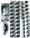
Bipolar cells. (A and B) IRM and DIC images taken 10 s apart. Small arrows indicate the direction of lateral forces compressing the substratum at each lamellipodium. The central region ({) produced few wrinkles in front of the cell. Large arrows show the direction of motion. (C) A pair of lamellipodia stretched the substratum between them (double-headed arrow). The larger lamellipodium (left) migrated faster than the smaller one, causing the cell to turn right (curved arrow). (D) Another cell that was being turned by a dominant lamellipodium, outlined in the image shown and at its position 50 s later. Bar, 10 μm.
Figure 10
Figure 10
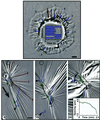
The fibroblast lamellum pulls rearward and the tail pulls forward. These images were focused on the substratum to show crinkles located underneath the cell body and wrinkles extending out from the cell; the outline of the cell is taken from images acquired 15 s later at a higher focal plane. Note that the time is in minutes. Forces estimated for wrinkles 1–4 at time 0 were 265, 500, 480, and 800 nN, respectively. The substratum was compressed by the cell when it formed a tail and contracted, as shown by two substratum markers in front of and behind the cell (arrowheads connected by a double-arrow line; separation quantitated in graph inset [24 min]). A second marker located farther in front of the cell was also pulled rearward between 12.5 and 19 min. Contraction of this cell and others outside of the field of view caused large shifts in the substratum, and individual marker trajectories reflect all of these movements. To better visualize the relative displacements of markers, the images at 0 and 19 min were shifted so that a reference marker behind the cell (circled) was positioned at the same location in the image. The reference marker had moved out of the field of view in the last image shown (24 min), and no correction was applied; hence, the displacement of all features in the image contains a large upward-right component. Bar, 20 μm.
Figure 11
Figure 11
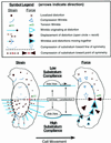
Summary of keratocyte traction forces inferred from substratum deformation. The drawings show average patterns of deformation in elastic substrata (left) and traction forces (right) produced by locomoting keratocytes. The upper part of the diagram (left side of the cell) indicates observations on stiff substrata that are not greatly deformed by the cell, remaining nearly flat under the cell body (see diagrammatic “Side View”), whereas the lower part of the diagram (right side of the cell) refers to highly compliant substrata that are greatly deformed by the cell and are depressed by the cell body. Symbols referring to strain and traction force are defined in the legend. The trajectories of force spots (filled circles) and wrinkles (curved lines) given by broken arrows refer to instantaneous displacement in the reference frame of the cell; individual markers generally do not follow these trajectories over time because of cell movement.
Figure 12
Figure 12
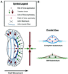
Mechanical and structural model of keratocyte locomotion. (A) Schematic diagram of a proposed two-phase mechanism of keratocyte locomotion. In the first phase, rearward-directed forces generated by the actin and myosin filament meshwork in the anterior lamellipodium pull the front of the cell body forward. In the second phase, higher lateral forces generated by actin-myosin fibers oriented across the cell body cause adhesions to detach, pulling the flanks and posterior cell body inward and forward. The midline represents a line of morphological, structural, and lateral force symmetry. A second line of symmetry is defined by smaller forces about the boundary of the lamellipodium and the cell body. These two lines cross to define a “point” of force symmetry. The large arrows in front of the cell refer to stronger lateral forces generated by transverse fibers, and the small arrows refer to weaker forces generated by network contraction, the net direction of which is parallel to the direction of motion. (B) Frontal view showing alternative consequences of transverse fiber contraction. (Top) Contraction of a cage of fibers tends to cause the cell body to round up on a compliant substratum that is easily pulled in by the flanks and depressed by the cell body; the cell body can also round up if it loses adhesion to the substratum. (Bottom) Internal shortening of curved transverse fibers causes them to straighten if they remain attached to stiff substrata at their ends. The fibers press inward on the cell body (down in the drawing), squeezing cytoplasm out toward the flanks.

Similar articles

Cited by

References

    1. Abercrombie M, Heaysman JEM, Pegrum SM. The locomotion of fibroblasts in culture. I. Movements of the leading edge. Exp Cell Res. 1970;59:393–398. - PubMed
    1. Abraham VC, Krishnamurthi V, Taylor DL, Lanni F. The actin-based nanomachine at the leading edge of migrating cells. Biophys J. 1999;77:1721–1732. - PMC - PubMed
    1. Anderson K, Wang Y-L, Small JV. Coordination of protrusion and translocation of the keratocyte involves rolling of the cell body. J Cell Biol. 1996;134:1209–1218. - PMC - PubMed
    1. Bailey B, Farkas DL, Taylor DL, Lanni F. Enhancement of axial resolution in fluorescence microscopy by standing-wave excitation. Nature. 1993;366:44–48. - PubMed
    1. Bereiter-Hahn J, Luers H. The role of elasticity in the motile behavior of cells. In: Akkas N, editor. Biomechanics of Active Movement and Division of Cells, NATO ASI Series. H84. Berlin: Springer-Verlag; 1994. pp. 181–230.

Publication types