. 2024 Jul 16;121(29):e2409334121.
doi: 10.1073/pnas.2409334121. Epub 2024 Jul 10.

Structure of the flotillin complex in a native membrane environment

Affiliations

Structure of the flotillin complex in a native membrane environment

Ziao Fu et al. Proc Natl Acad Sci U S A. .

Abstract

In this study, we used cryoelectron microscopy to determine the structures of the Flotillin protein complex, part of the Stomatin, Prohibitin, Flotillin, and HflK/C (SPFH) superfamily, from cell-derived vesicles without detergents. It forms a right-handed helical barrel consisting of 22 pairs of Flotillin1 and Flotillin2 subunits, with a diameter of 32 nm at its wider end and 19 nm at its narrower end. Oligomerization is stabilized by the C terminus, which forms two helical layers linked by a β-strand, and coiled-coil domains that enable strong charge-charge intersubunit interactions. Flotillin interacts with membranes at both ends; through its SPFH1 domains at the wide end and the C terminus at the narrow end, facilitated by hydrophobic interactions and lipidation. The inward tilting of the SPFH domain, likely triggered by phosphorylation, suggests its role in membrane curvature induction, which could be connected to its proposed role in clathrin-independent endocytosis. The structure suggests a shared architecture across the family of SPFH proteins and will promote further research into Flotillin's roles in cell biology.

Keywords: Flotillin structure; SPFH domain; native membrane.


Conflict of interest statement

Competing interests statement:The authors declare no competing interest.

Figures
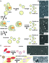
Fig. 1.
Fig. 1.
Flotillin vesicle preparation from various cell membranes. (A) Schematic representation of three methods employed for the preparation of Flotillin vesicles from HEK293 GnTl cells. The endoplasmic reticulum (ER) membrane is depicted in light gray, the PM in dark gray, the nuclei in brown, and Flotillin (FLOT) in blue. 1) Preparation of Flotillin vesicles from the PM using NEM and Ca2+, resulting in native membrane vesicles (NMVs). Following sonication, two orientations of Flotillin were observed: inside-out, where Flotillin is outside the vesicles, and outside-out, where Flotillin is inside the vesicles. 2) Procedure for obtaining total membrane vesicles primarily through sonication. 3) Method for isolating exosomes secreted from HEK293 GnTl cells. (B) Representative micrographs illustrating Flotillin vesicles from the PM (Top), total membrane (Middle), and exosomes (Bottom). Flotillin clusters were observed within vesicles, facing either outside (Top) or inside (Middle) the vesicle. (Scale bar, 50 nm.) White arrows highlight Flotillin. (C) Flotillin presence in erythrocyte vesicles generated by sonication, depicted in a representative micrograph (Right). Erythrocytes are colored in red, Flotillin in blue. (Scale bar, 50 nm.) White arrows highlight Flotillin. (D) Observation of Flotillin in cryoelectron tomograms of erythrocyte membrane patches unroofed by shear force. Examples from the same membrane patches show erythrocytes stuck on the cryo-EM grid support (yellow surface) unroofed using shear force. The bottom membrane (pink) of erythrocytes containing Flotillin was imaged using cryoelectron tomography, with tomographic slices of Flotillin shown on the right. (Scale bar, 20 nm.)
Fig. 2.
Fig. 2.
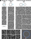
Flotillin orientation relative to vesicles. (A) Sideview of Flotillin vesicles illustrates three cases: 40% of Flotillin is inside the vesicle (referred to as outside-out, Left), while 60% of Flotillin is outside the vesicles (inside-out). In the inside-out configuration, one-third of the Flotillin have a free narrow end, and two-thirds bind to a second vesicle at the narrow end. (B) Examples of Flotillin vesicles showcasing outside-out (Left), inside-out (Middle), and inside-out double membrane (Right) orientations. (Scale bar, 50 nm.) (C) Representative 2D classifications of Flotillin from vesicles displaying various orientations. (Scale bar, 10 nm.) (D) High-resolution 2D class average depicts 44 subunits in the top view. Each circle represents one subunit, with the starting one in red and the ending one in white.
Fig. 3.
Fig. 3.
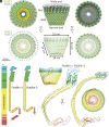
The overall structure of the Flotillin complex and domain organization. (A) Views from the bottom (cytoplasmic view), side, and top of the cryo-EM map of the Flotillin complex. Flotillin1 and Flotillin2 are denoted in yellow and blue, respectively, associated with white-shaded cryo-EM density corresponding to the membrane. Regions corresponding to the Rim, Wall, Wide end and Narrow end are labeled adjacent to their respective locations in the cryo-EM map. (B) Views from the bottom (cytoplasmic view), side, and top of the atomic model representing the Flotillin complex. Labels accompany each part, providing dimensions for the Flotillin complex. (C) Schematic depiction illustrating the domain organization and secondary structure topology of Flotillin1 and Flotillin2. Individual domains are colored: SPFH1 in cyan, SPFH2 in green, Flotillin α-helical barrel in yellow, cap helix (CapH) in orange, β-barrel in orange red, and C-terminal domain (CTD) in red. Flotillin1 and Flotillin2 differ in their CTDs. (D) The atomic model of the dimer of Flotillin1 and Flotillin2. Secondary structural motifs are color-coded as described in (C). Dashed lines delineate the dimer's positions relative to the entire Flotillin complex from both side and bottom views.
Fig. 4.
Fig. 4.
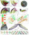
Structure and organization of the narrow end and wall regions in the Flotillin complex. (A) Bottom view (Right) of the Flotillin complex displaying eight subunits, each uniquely colored. In the middle, a zoomed-in view of the boxed region highlights the cartoon representation of the narrow end, consisting of eight subunits (F1a, F2a, F1b, F2b, F1c, F2c, F1d, F2d), with their corresponding cryo-EM density shown on the left. (B) Top view of the Flotillin complex’s cryo-EM density (Left) and cartoon representation (Middle). On the right, the side view of the same narrow end is presented. (C) Amino acids involved in subunit interactions, with colors indicating amino acids from the same subunits. Dashed lines represent hydrophobic interactions between the first (Left) and second (Right) helix layers, while solid lines indicate intersubunit ionized hydrogen bonds. (D) Zoomed-in top view detailing interactions in the narrow end highlighting the ionized hydrogen bonds. (E) Zoomed-in side view detailing interactions in the narrow end highlighting close contacts that would permit van der Waals interaction. (F) Side view of the Flotillin complex with eight Wall helices separately colored on the left. On the right, both outside-view and inside-view of the eight Wall helices highlight charged residues involved in forming ionized hydrogen bonds (colored in green and magenta), with interactions represented by solid purple lines connecting the α-carbons of interacting amino acids. (G) Wheel plot illustrating amino acids from four neighboring subunits involved in intersubunit ionic hydrogen bonds. The top part shows residues outside the Flotillin complex (labeled as O), and the bottom part shows inside residues (labeled as I). Dashed box regions correspond to the zoomed-in view from (F), displaying detailed interactions between charged amino acids involved in ionic hydrogen bonding.
Fig. 5.
Fig. 5.
Membrane association of the Flotillin complex. (A) Side view (Left), intersection view (Middle), and PM intersection view at the plane indicated by the dashed line from the middle panel. Individual domains are distinctly colored: SPFH1 in cyan, SPFH2 in green, CC1 in yellow, CC2 in orange, and CTD in red. The membrane is depicted in gray. (B) Zoomed-in view of the SPFH1 domain from the dimer of Flotillin1 and Flotillin2 cartoon representation (Right), as indicated by the dashed boxed region from the 20° tilted side view on the left. Hydrophobic residues and potential lipidated cysteines, halfway inserted in the inner leaflet of the membrane (above the solid line), are highlighted in yellow and labeled accordingly. (C) Reconstruction of the Flotillin complex associated with two membranes. The dashed box region highlights potential parts involved in membrane association in the narrow end. The sequence of the unstructured region of Flotillin 1 and Flotillin 2 CTDs is shown, with an arrow indicating the beginning of the unstructured region at CTDs. Membrane positions are depicted with gray lines and labeled. (D) Intersection view of cryo-EM maps of the Flotillin complex outside (in yellow) and inside (blue) vesicles. An overlapping view of both cryo-EM maps with a focus on the conformational change in the SPFH domain (dashed box). The bending motion of the SPFH domain in the Flotillin complex is indicated using colored lines and a directional arrow. The potential site of phosphorylation is marked by a filled red circle containing the letter “P.”
Fig. 6.
Fig. 6.
Common architecture of the SPFH protein family and their functional implications. (A) Predicted tetrameric protein complexes of Flotillin1/2, Erlin1/2, Stomatin-like protein 2 (SLP2), HlfK/C, Prohibitin1/2, and Stomatin by Alphafold2. The complexes contain SPFH2, CC1, and CC2 domains, with monomers color-coded from green to red representing N terminus to C terminus. The table lists the number of amino acids in the CC1 domain of each protein. (B) General model illustrating the formation of a basket-like structure associated with the membrane by SPFH proteins. Varying lengths of SPFH proteins result in differences in the area they occupy on the membrane and the size of their complexes. (C) Representative cryo-EM 2D classification averages of the Flotillin complex, presumably Stomatin-like protein 2, and Stomatin determined from NMV preparations. (Scale bar, 20 nm.)

Comment in

Similar articles

Cited by

References

    1. Bickel P. E., et al. , Flotillin and epidermal surface antigen define a new family of caveolae-associated integral membrane proteins*. J. Biol. Chem. 272, 13793–13802 (1997), 10.1074/jbc.272.21.13793. - DOI - PubMed
    1. Schulte T., Paschke K. A., Laessing U., Lottspeich F., Stuermer C. A. O., Reggie-1 and Reggie-2, two cell surface proteins expressed by retinal ganglion cells during axon regeneration. Development 124, 577–587 (1997), 10.1242/dev.124.2.577. - DOI - PubMed
    1. Tavernarakis N., Driscoll M., Kyrpides N. C., The SPFH domain: Implicated in regulating targeted protein turnover in stomatins and other membrane-associated proteins. Trends Biochem. Sci. 24, 425–427 (1999), 10.1016/S0968-0004(99)01467-X. - DOI - PubMed
    1. Singh J., et al. , Cross-linking of the endolysosomal system reveals potential flotillin structures and cargo. Nat. Commun. 13, 6212 (2022), 10.1038/s41467-022-33951-0. - DOI - PMC - PubMed
    1. Glebov O. O., Bright N. A., Nichols B. J., Flotillin-1 defines a clathrin-independent endocytic pathway in mammalian cells. Nat. Cell Biol. 8, 46–54 (2006), 10.1038/ncb1342. - DOI - PubMed

LinkOut - more resources