. 2024 Jun 25;24(13):3252-3264.
doi: 10.1039/d4lc00107a.

A fluid-walled microfluidic platform for human neuron microcircuits and directed axotomy

Affiliations

A fluid-walled microfluidic platform for human neuron microcircuits and directed axotomy

Federico Nebuloni et al. Lab Chip. .

Abstract

In our brains, different neurons make appropriate connections; however, there remain few in vitro models of such circuits. We use an open microfluidic approach to build and study neuronal circuits in vitro in ways that fit easily into existing bio-medical workflows. Dumbbell-shaped circuits are built in minutes in standard Petri dishes; the aqueous phase is confined by fluid walls - interfaces between cell-growth medium and an immiscible fluorocarbon, FC40. Conditions are established that ensure post-mitotic neurons derived from human induced pluripotent stem cells (iPSCs) plated in one chamber of a dumbbell remain where deposited. After seeding cortical neurons on one side, axons grow through the connecting conduit to ramify amongst striatal neurons on the other - an arrangement mimicking unidirectional cortico-striatal connectivity. We also develop a moderate-throughput non-contact axotomy assay. Cortical axons in conduits are severed by a media jet; then, brain-derived neurotrophic factor and striatal neurons in distal chambers promote axon regeneration. As additional conduits and chambers are easily added, this opens up the possibility of mimicking complex neuronal networks, and screening drugs for their effects on connectivity.


Conflict of interest statement

P. R. C. and E. J. W. co-founded, and hold equity in, IotaSciences Ltd. The same company provides financial support to F. N., plus reagents and equipment for the study. Oxford University Innovation – the technology transfer company of The University of Oxford – has filed patent applications on behalf of P. R. C. and E. J. W. covering technologies used in this study.

Figures

Fig. 1
Fig. 1. Fabrication and operation of fluid-walled circuits. (A) Fabrication. (i) In a standard polystyrene Petri dish, a thin layer of cell-culture medium is overlaid by an immiscible, transparent, and bio-inert fluorocarbon (FC40). (ii) Additional FC40 is jetted (480 μl min−1) through a nozzle mounted on a 3D-traverse. (iii) The submerged jet sweeps away medium, to leave fluid walls of FC40 pinned to the dish along the path of the traverse. (B) Array of dumbbells after filling each with red and blue dyes. (i and ii) Top and side views of dish. (iii) Zoomed-in image of one dumbbell (conduit length = 1 mm). (C) Comparing properties of solid PDMS walls used in conventional devices, with fluid ones. (i) Access to a conventional device is only through inlet and outlet ports. (ii) Medium can be pipetted into or out of any point in a fluid-walled circuit as liquid–liquid interfaces are easily pierced to re-heal automatically on withdrawal. (iii) Fluid walls can be destroyed at any time, and different ones recreated on demand.
Fig. 2
Fig. 2. Ensuring liquid pipetted into the left of a dumbbell remains there. P = pressure. (A) Principles. (i) A dumbbell is flow-free after fabrication. (ii) Medium (4 μl) is added to the right-hand chamber; this generates a high local Laplace pressure. When 1 μl is immediately added to the left-hand chamber (creating a lower local Laplace pressure), resulting left-ward flow through the conduit prevents any of the 1 μl from moving to the right. (iii) Eventually the system equilibrates, and flow ceases. (B) Pressure difference drives flow. (i) Before filling. (ii) Immediately after filling with different volumes. (iii) After 24 h, chamber volumes have almost equalised due to leftward flow. (C) After adding 4 μl blue dye to the right and 1 μl red dye to the left, no red dye flows rightward (top views). (i) Before adding dyes (dotted line marks dumbbell footprint). (ii) Immediately after adding dyes. (iii) After 24 h, red dye remains confined in its chamber (which now also contains blue dye). (D) Changes in pressure (i) and volume (ii) of right- (blue) and left-hand (red) chambers determined after measuring chamber heights and calculating values using eqn (1) (Pright and Pleft) and eqn (3), respectively. Black curve: pressure difference between chambers. Each dot represents the mean value of 3 technical replicates, and grey areas the associated standard deviations.
Fig. 3
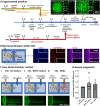
Fig. 3. Timelines and culture conditions used to model and study unidirectional outgrowth of cortical neurons. (A) Timelines. Yellow and red lines show protocols for generating CNs and striatal MSNs from iPSCs using standard methods; blue line describes those involved in making and operating fluid-walled dumbbells. Insets: After plating transduced CNs in left-hand chambers, live-cell images (collected on d −1 and 18) show NGN2-GFP fluorescence in parts of dumbbells (dotted white lines show circuit edges). (B) Immunostaining shows compartmentalisation of neuronal domains in CNs (d 25). Cartoon: CNs in left-hand chamber, CN medium (but no MSNs) in distal one. Nuclei (DAPI) and MAP2-positive dendrites are confined within the chamber, while only SMI312-positive axons grow into the conduit (dotted white lines show circuit edges). (C) Effects of varying distal-chamber content on axonal outgrowth. In all cases, CNs expressing NGN2-GFP are plated in CN medium in left-hand chambers. Top: Cartoons indicating chamber contents. Bottom: Live-cell epifluorescence images of left end of conduit (d 20); axons extend into conduits in all three cases. (i) Monoculture control. (ii) Positive control with regenerative medium in distal chamber (CN medium + 10-fold higher concentration of 100 ng ml−1 BDNF). (iii) MSNs + MSN medium in distal chamber (this condition attempts to promote connectivity between cortex and striatum seen in vivo). (D) Quantitative analysis of axonal outgrowth seen in (C). Outgrowth (fold difference) is difference in area covered by GFP-expressing neurites in conduits between d 0 and d 20, normalised for GFP-positive conduit area on d 0 as a function of the number of cells, and expressed relative to their control. Each dot represents a healthy control-derived line from one differentiation. N = 2 iPSC lines, n = 2–3 differentiations per line. One-way ANOVA with Bonferroni correction; p > 0.05.
Fig. 4
Fig. 4. Modelling unidirectional pathway between cortex and striatum. Cortical axons marked with NGN2-GFP grow from the left chamber through the conduit into the distal chamber containing MSNs (DAPI – blue – nuclei, MAP2 – red – dendrites, SMI312 – purple – axons, NGN2-GFP – green – transduced CNs, DARPP32 – yellow – MSN marker; merges indicated). (A) Top-view schematic of the cortex-striatum circuit in a fluid-walled dumbbell. CNs are seeded in the left chamber and cultured for 6 days, then MSNs are plated in the distal (right) chamber; after growth for another 25 days, cells are immunolabelled. White boxes indicate areas imaged below using various markers. (B) MAP2-positive dendrites and NGN2-GFP are found throughout the CN chamber (but not DARPP32-expressing MSNs). (C) MSN nuclei remain where seeded and develop MAP2-positive dendrites; they are joined by SMI312-positive CN axons from the left-hand chamber. (D) Axons containing NGN2-GFP from transduced CNs are intertwined amongst MAP2- and DARPP32-positive neurons in the striatal chamber.
Fig. 5
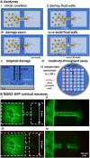
Fig. 5. Axotomy assay on fluid-walled microfluidics. (A) Schematics illustrating localized axotomy. (i) Circuit before starting axotomy. (ii) Fluid walls are destroyed; cells remain attached to Geltrex within the dumbbell footprint. (iii) The traverse moves a nozzle that jets medium onto axons and cuts them. (iv) New fluid walls are jet-printed (using an FC40 jet) to form a new dumbbell slightly larger than the original one; after filling the new dumbbell, axons regrow. (v) Higher-magnification schematic of the submerged media jet in action targeting axons to generate localised damage. (vi) Overview. Red lines illustrate the path followed by the medium jet nozzle while damaging 21 dumbbells (7 × 3 array) in a single 6 cm Petri dish in less than 90 seconds. Solid lines indicate the path already covered; dashed lines show future nozzle positions. (B) Representative live-cell fluorescent images of CNs expressing NGN2-GFP pre- and post-axotomy. (i and ii) Dashed lines mark edges of dumbbell footprints before and after axotomy. (iii and iv) Higher magnification images taken before and after axotomy.
Fig. 6
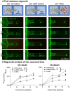
Fig. 6. Effects of distant target-derived factors on regrowth of cortical axons after damage. (A) Schematic and representative live-cell fluorescent images of CNs expressing NGN2-GFP taken 0–84 h after axotomy. (B) Fraction of axotomized area re-covered by axons derived from two different healthy control iPSC lines (SFC-156-003, SFC-856-03). N = 2–3 differentiations per iPSC line, * p < 0.05, ** p < 0.01, *** p < 0.001, two-way ANOVA with Bonferroni correction test. (SFC156-03: CN-CN medium versus CN-BDNF medium, p > 0.05 at 36 and 60 hours, p < 0.01 at 84 hours; CN-CN medium versus CN-MSN, p < 0.0001 at 36 hours, p < 0.001 at 60 and 84 hours; SFC856-03: CN-CN medium versus CN-BDNF medium, p < 0.001 at 36 hours, p < 0.05 at 60 and 84 hours; CN-CN medium versus CN-MSN, p < 0.01 at 36 and 84 hours, p < 0.05 at 60 hours; two-way ANOVA with Bonferroni correction test). Furthermore, BDNF and MSNs exert comparable positive effect on cortical axonal regeneration (for both iPSC lines, CN-BDNF medium versus CN-MSN p > 0.05, two-way ANOVA with Bonferroni correction test).

Similar articles

Cited by

References

    1. Iannielli A. Ugolini G. S. Cordiglieri C. Bido S. Rubio A. Colasante G. Valtorta M. Cabassi T. Rasponi M. Broccoli V. Cell Rep. 2019;29:4646–4656.e4. doi: 10.1016/j.celrep.2019.11.111. - DOI - PMC - PubMed
    1. Virlogeux A. Moutaux E. Christaller W. Genoux A. Bruyere J. Fino E. Charlot B. Cazorla M. Saudou F. Cell Rep. 2018;22:110–122. doi: 10.1016/j.celrep.2017.12.013. - DOI - PubMed
    1. Miura Y. Li M.-Y. Birey F. Ikeda K. Revah O. Thete M. V. Park J.-Y. Puno A. Lee S. H. Porteus M. H. Paşca S. P. Nat. Biotechnol. 2020;38:1421–1430. doi: 10.1038/s41587-020-00763-w. - DOI - PMC - PubMed
    1. Taylor A. M. Dieterich D. C. Ito H. T. Kim S. A. Schuman E. M. Neuron. 2010;66:57–68. doi: 10.1016/j.neuron.2010.03.022. - DOI - PMC - PubMed
    1. Luo X. Chen J.-Y. Ataei M. Lee A. Biosensors. 2022;12:58. doi: 10.3390/bios12020058. - DOI - PMC - PubMed

Publication types

MeSH terms

Substances