Review
. 2024 Jan 1;14(1):33-55.
doi: 10.7150/thno.90093. eCollection 2024.

Tumor-on-a-chip models combined with mini-tissues or organoids for engineering tumor tissues

Affiliations
Review

Tumor-on-a-chip models combined with mini-tissues or organoids for engineering tumor tissues

Hanjun Hwangbo et al. Theranostics. .

Abstract

The integration of tumor-on-a-chip technology with mini-tissues or organoids has emerged as a powerful approach in cancer research and drug development. This review provides an extensive examination of the diverse biofabrication methods employed to create mini-tissues, including 3D bioprinting, spheroids, microfluidic systems, and self-assembly techniques using cell-laden hydrogels. Furthermore, it explores various approaches for fabricating organ-on-a-chip platforms. This paper highlights the synergistic potential of combining these technologies to create tumor-on-a-chip models that mimic the complex tumor microenvironment and offer unique insights into cancer biology and therapeutic responses.

Keywords: Biofabrication; Cancer research; Organoids; Tumor microenvironment; Tumor-on-a-chip.


Conflict of interest statement

Competing Interests: The authors have declared that no competing interest exists.

Figures

Figure 1
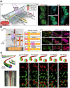
Figure 1
Fabrication of mini-tissues/organoid using bioprinting system. (A) (i) Schematic diagram of in situ E-field stimulation and (ii) optical, live (green)/dead (red), SEM, and DAPI (blue)/phalloidin (green) images of hASCs fabricated W/ or W/O E-fields, where in situ E-field simulation evoked favourable cellular responses. Adapted with permission from , copyright Wiley 2021. (B) Schematic illustration of (i) the fabrication process of 3D bioprinting using a modified core/shell nozzle consisting of two sheath inlets and, and (ii) myotendinous junction (MTJ) unit. Adapted with permission from , copyright Wiley 2022. (C) Schematic illustration of inkjet bioprinting system containing several components including piezoactuator-attached inkjet nozzle, a waveform generator, a pneumatic controller, a bioink reservoir. Adapted with permission from , copyright MDPI 2022. (D) (i) Schematical diagram and (ii) optical images of drop-on-demand bioprinting method. (iii) Representative images of various patterns of dispensed solution volume by the drop-on-demand printing system. Adapted with permission from , copyright MDPI 2020.
Figure 2
Figure 2
Various fabrication methods of cell-spheroids. Various schematical illustration of spheroid formations including (A) hanging drop that utilizes gravitational forces and surface tension to induce cell aggregation, (B) non-adherent surface which applies low attachment surfaces to induce self-assembly of cells into spheroids, (C) micro-patterned mold which utilizes seeding cells into micropatterned mold, and (D) microfluidic method which utilizes immiscible fluids and precise control of the flowrates to generate spheroids.
Figure 3
Figure 3
Fabrication of mini-tissues/organoid using cell-spheroids. (A) (i) Schematic diagrams of the co-culture microfluidic device and (ii) computational fluid dynamic model of the heatmaps of) demonstrating rapid accumulation HGF (hepatocyte growth factor) using COMSOL. Adapted with permission from , copyright MDPI 2023. (B) (i) “Bio-dot printing” fabrication procedure using polycaprolactone printing and cell spheroids, and (ii) Microscopy and fluorescence images of MDAMB231 and/or NIH3T3 cell spheroids demonstrating 3D spheroid invasion. Adapted with permission from copyright Wiley 2020. (C) (i) Schematic diagram of cell/spheroid electrospinning process and (ii) scanning electron microscopy images demonstrating embedded cells (C-scaffold) and cell spheroid (S-scaffold) in electrospun PCL nanofibers. Adapted with permission from copyright Ivyspring 2021.
Figure 4
Figure 4
Fabrication of mini-tissues/organoid using microfluidic system. (A) (i) Schematic diagrams, and (ii) live (green)/dead (red) and DAPI (blue)/phalloidin (green) images demonstrating cell-bead laden structures fabricated with the microfluidic device. Adapted with permission from , copyright Wiley 2022. (B) (i) Schematic diagram of the T-junction microfluidic system and the influence of the Rayleigh instability of cell-laden methacrylated gelatin (Gel-Ma) and collagen/polyethylene glycol diacrylate (PEGDA). (ii) Live (green)/dead (red) and DAPI (blue)/phalloidin (red) images of cells in fiber, rosary, and bead core structures. Adapted with permission from , copyright Elsevier 2023. (C) Schematic diagram of various geometries of microchannels (i-ii) and (iii) optical images of the bioink flowing process. Adapted with permission from , copyright Elsevier 2021.
Figure 5
Figure 5
Applications of 3D bioprinted tissue-constructs incorporated in TOC. (A) (i) Schematic illustrations of the bioprinting process for the organ-on-a-chip (OOC), and (ii) optical images of the perfusion of OOC and flurescent images of DAPI (blue)/CD31 (green) demonstrating vascularization of perfuable OOC. Adapted with permission from , copyright Wiley 2021. (B) Schematic showing (i) native and (ii) designed lymphatic-blood system of tumor microenvironment. (iii-vi) Schematic diagram of the fabrication process of the OOC demontrating perfusable blood (red) and flymphatic (yellow) hollow tubes. Adapted with permission from , copyright Wiley 2019. (C) (i) schematical diagram illustrating 3D bioprinting of multistage microfluidic OOC and (ii) confocal imaging demonstrating HUVEC (red) and pericyte cells (blue) within the OOC. Adapted with permission from , copyright AAAS 2021.
Figure 6
Figure 6
Cell-spheroids incorporated in TOC applications. (A) (i) Tumor microenvironment (TME) schematic illustration between interactional dynamics of pre-metastatic tumor and neutrophils and (ii) optical images demonstrating tumor spheroids incased within microwells. Adapted with permission from , copyright IOP publishing 2021. (B) (i) Schematic illustration of vascularized tumor spheroid organ-on-a-chip (OOC) comprised of five microchannels and (ii) fluorescence images of Eca-109 and HUVEC cells demonstrating vascularized tumor spheroids. Adapted with permission , copyright ACS publishing 2022. (C) Schematics and optical images of microfluidic OOCs containing MCF-7 cells demonstrating evaluation of nanoparticle penetration, and (ii) bright-field and fluorescent images of spheroid arrays containing 160 MCF-7 tumor spheroids. Adapted with permission , copyright Wiley 2019.
Figure 7
Figure 7
Microfluidic-based TOCs. (A) (i) Normal optical and (ii) fluorescent images showing live (green)/dead (red) microvasculature-based organ-on-a-chip OOC containing brain tumor stem-like cells. (iii) Finite element analysis (FEA) results of flow velocity profile measured using COMSOL software and (iv) immunofluorescent images (VE-cadherin and vWF), cross-sectional images of the microvessels. Adapted with permission , copyright Wiley 2019. (B) (i) Schematic diagram and optical images of OOC consisting of a central culture compartment and perfusion mechanism (blue: trypan blue). (ii) Evaluation of hypoxia of a PMMA-incorporated OOC. Adapted with permission , copyright MDPI 2019. (C) (i) A 3D heatmap and design of an OOC, (ii) fluorescent images demonstrating prevascularization of OOC, and (iii) schematic and optical images of endothelial cell sprout formations. Adapted with permission copyright AAAS 2019. (D) (i) Schematic illustration and optical images of OOC consisting of blood vessels and pancreatic cancer ducts, and distance of pancreatic ductal adenocarcinoma cell invasion distance. (ii) Fluorescent images of YFP PD7591 cells invading the blood vessel. Adapted with permission copyright AAAS 2019.

Similar articles

Cited by

References

    1. Zugazagoitia J, Guedes C, Ponce S, Ferrer I, Molina-Pinelo S, Paz-Ares L. Current challenges in cancer treatment. Clinical therapeutics. 2016;38:1551–66. - PubMed
    1. Imamura Y, Mukohara T, Shimono Y, Funakoshi Y, Chayahara N, Toyoda M. et al. Comparison of 2D-and 3D-culture models as drug-testing platforms in breast cancer. Oncology reports. 2015;33:1837–43. - PubMed
    1. Chen G, Xu Y, Kwok PCL, Kang L. Pharmaceutical applications of 3D printing. Additive Manufacturing. 2020;34:101209.
    1. Ali MA, Hu C, Yttri EA, Panat R. Recent advances in 3D printing of biomedical sensing devices. Advanced functional materials. 2022;32:2107671. - PMC - PubMed
    1. Derakhshanfar S, Mbeleck R, Xu K, Zhang X, Zhong W, Xing M. 3D bioprinting for biomedical devices and tissue engineering: A review of recent trends and advances. Bioactive materials. 2018;3:144–56. - PMC - PubMed