. 2022 Nov 21;26(1):105624.
doi: 10.1016/j.isci.2022.105624. eCollection 2023 Jan 20.

Computational characterization of recombinase circuits for periodic behaviors

Affiliations

Computational characterization of recombinase circuits for periodic behaviors

Judith Landau et al. iScience. .

Abstract

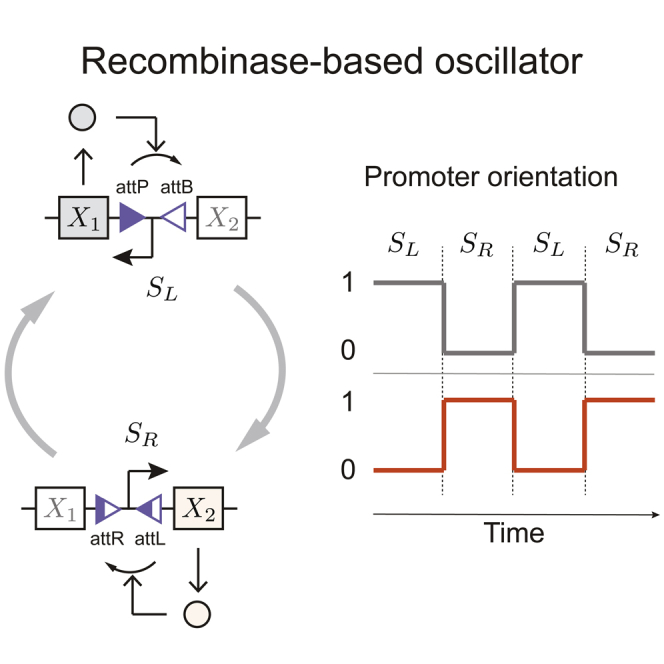
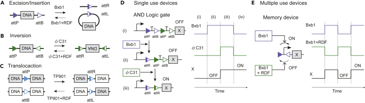
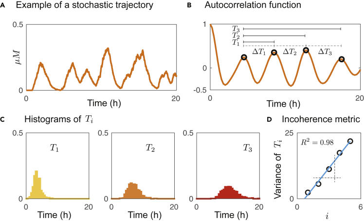
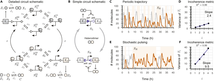
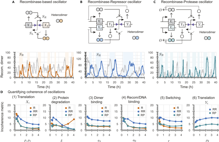
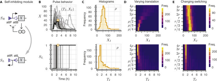
Recombinases are site-specific proteins found in nature that are capable of rearranging DNA. This function has made them promising gene editing tools in synthetic biology, as well as key elements in complex artificial gene circuits implementing Boolean logic. However, since DNA rearrangement is irreversible, it is still unclear how to use recombinases to build dynamic circuits like oscillators. In addition, this goal is challenging because a few molecules of recombinase are enough for promoter inversion, generating inherent stochasticity at low copy number. Here, we propose six different circuit designs for recombinase-based oscillators operating at a single copy number. We model them in a stochastic setting, leveraging the Gillespie algorithm for extensive simulations, and show that they can yield coherent periodic behaviors. Our results support the experimental realization of recombinase-based oscillators and, more generally, the use of recombinases to generate dynamic behaviors in synthetic biology.

Keywords: Biocomputational method; Bioengineering; Synthetic biology.


Figures

None
Graphical abstract
Figure 1
Figure 1
Serine integrases and their applications in synthetic circuits We summarize the most important functions of serine integrases (panels A–C) and their relevant applications (panels D and E). There are two families of recombinases: tyrosine recombinases and serine recombinases. All recombinases are site-specific proteins that can rearrange DNA, performing, for example, excision/insertion, inversion, and translocation. Serine integrases are a subfamily of serine recombinases, each of which has a cognate Recombination Directionality Factor (RDF) that allows the serine integrase to reverse-rearrange DNA. We consider three examples involving the serine integrases Bxb1, φ C31, and TP901, with cognate attP and attB binding sites. When the attP and attB binding sites have the same orientation, Bxb1 monomers form a dimer, bind to the two specific sites, and excise the DNA segment in between, as shown in panel A (excision/insertion). When the attP and attB binding sites point in opposite directions, φ C31 binds to them and inverts the DNA between the binding sites, as shown in panel B (inversion). When the attP and attB binding sites are not in the same region of DNA, TP901 can bind to the attP and attB binding sites and translocate the DNA strands, as shown in panel C (translocation). In all the above examples, adding a recombination directional factor (RDF) enables the recombinases to recognize the binding sites attL and attR present after the rearrangements described, and therefore to reverse them. Tyrosine recombinases can perform the DNA rearrangements described, among others, but not reverse them, examples including Cre, Vre, and FLP. The exception to this is the pair of tyrosine recombinases FimE and HbiF that can reverse the DNA recombination completed by the other. Recombinases have been used within logic gate circuits, such as the AND gate shown in panel D. In this example, two transcription terminators are between the attP and attB binding sites for two different and orthogonal recombinases, Bxb1 and φ C31, shown in purple and green, respectively. In the absence of both recombinase inputs, the transcription of gene X is suppressed (OFF). When Bxb1 is added, it excises the first terminator. However, the transcription remains suppressed (OFF), because the second terminator is still present. When φ C31 is also added, it excises the second terminal, which finally activates the transcription of gene X (ON). Hence, two recombinase inputs (Bxb1 and φ C31) are needed to activate the circuit. One major disadvantage of recombinase-based logic gates is that the irreversibility of the DNA rearrangement means they can only be operated a single time. This circuit would require the cognate RDFs of these integrases to insert the DNA that was excised and thus be a multiple-use device. There are few demonstrations of multiple-use, dynamic devices built using recombinases. The first example was the engineering of a programmable switch, as shown in panel E. This pioneering work uses Bxb1 and its RDF to change the direction of the promoter controlling the production of X over multiple cell generations. An improved version of the programmable switch uses tyrosine recombinases FimE and HbiF, which are the only special cases of tyrosine recombinases that allow reversible DNA rearrangement. Other dynamical circuit designs based on recombinases include a negative feedback controller to track a ref. ,, some theoretical designs of toggle switches that incorporate multiple copies of the circuit, and a single-input counting circuit. The oscillatory behavior of a recombinase-based circuit has also been analyzed deterministically. Because recombinases can be used as a switch to turn on/off gene expression, they are well suited to build large Boolean logic circuits that can be hierarchically composed with a predictable response. In addition, self-excision recombinases were used to generate temporal responses such a pulses, and a cascade of self-excision mechanism can create a sequential pulse behavior that operates once. Because leaky expression of recombinases can jeopardize circuit operation (only few protein copies are necessary to carry out their function), methods to tightly control their production are necessary, for example via light-induction.
Figure 2
Figure 2
Incoherence metric for stochastic trajectories (A) Example of a stochastic trajectory with periodic behavior. (B) The autocorrelation function of the orange plot in (A) highlights the periodic cycles from the stochastic trajectory. Ti denotes the time interval between peak 1 and peak i+1, while the time interval between subsequent peaks i+1 and i is denoted as ΔTi. (C) Histograms showing the distributions of T1, T2, and T3, when their values are taken from multiple simulations. (D) The variance of Ti over multiple simulations plotted against i can be approximated as a line, whose slope is a metric for incoherence.
Figure 3
Figure 3
Architecture of a recombinase-based oscillator and incoherence of the period (A) Detailed set of reactions of the recombinase-based oscillator design consisting of two coupled, self-inhibiting modules on the same promoter: Recombinases X1 and X2 can each invert the promoter when it is controlling its own production, creating a tug-of-war-like behavior. The binding sites on either side of the promoter change back and forth at each inversion. (B) Simplified circuit representation that illustrates the two states of the promoter: left (SL) or right (SR). (C) Example of a periodic trajectory achieved using the parameters in Table S1: Concentration of X1 in gray and X2’s concentration is in orange. Light orange regions mark when the promoter points to the right (configuration SR) and white regions mark when it points to the left (configuration SL). (D) Incoherence metric: Slope of the line interpolating the variance of times Ti as a function of the peak index i computed over an ensemble of 500 simulations with the simulation conditions in (C) (See also Figure 2D). (E) Example of a trajectory exhibiting stochastic pulsing. (F) Incoherence metric plot for the simulation conditions in (E).
Figure 4
Figure 4
Analysis of the R, RR, and RP oscillator designs (A) Top: R oscillator design with a single inverting promoter that alternately controls the production of recombinases X1 (when it is pointing to the left, configuration SL) and X2 (when it is pointing to the right, configuration SR). Molecular sequestration is included through the heterodimerization of X1 and X2. Bottom: Trajectories of a single simulation showing the time evolution of the concentrations of X1 (gray) and X2 (orange) over time. The light orange stripes mark when the promoter points to the right (configuration SR), while white stripes mark when the promoter points to the left (configuration SL). (B) Top: RR oscillator design with a single inverting promoter that alternately controls the production of two different repressor proteins, Y1 and Y2, while recombinases X1 and X2 are produced constitutively and also heterodimerize. Bottom: Trajectories of a single simulation showing the time evolution of the concentrations X1 (gray) and X2 (blue). The colored stripes indicate the current promoter configuration (SR or SL). (C) Top: RP oscillator design with an inverting promoter that alternates between controlling the production of protease proteins Y1 and Y2, while recombinases X1 and X2 are produced constitutively with the ability to heterodimerize. Bottom: Trajectories of a single simulation showing the time evolution of X1 (gray) and X2 (teal). The colored stripes denote the current promoter configuration (SR or SL). (D) Analysis of the coherence of the R, RR, and RP designs for different parameter regimes. Each point on these plots represents the incoherence metric calculated using a collection of simulations using the multiplier value indicated on the x axis. All parameters used for our simulations are reported in Table S1 along with their nominal values. For our sensitivity analysis, in each plot, we vary the considered parameter value from 0.25 to 4 times its nominal value.
Figure 5
Figure 5
Analysis of the RA, RS, and NF oscillator designs (A) Top: RA oscillator design with a single inverting promoter that alternately controls the production of transcriptional activators Y1 and Y2, which respectively regulate the production of recomabinases dimers X1 and X2; the recombinase monomers undergo molecular sequestration through heterodimerization. Bottom: Trajectories of a single illustrative simulation showing the time evolution of the concentrations of X1 (gray) and X2 (blue) over time. The light color stripes mark when the promoter points to the right (configuration SR), while white stripes mark when the promoter points to the left (configuration SL). (B) Top: RS oscillator design with an inverting promoter that alternately regulates the production of small RNAs Y1 and Y2, which inhibit mRNA recombinases, preventing their transcription into X1 and X2, respectively. These recombinases are also able to heterodimerize. Bottom: Trajectories of a single simulation showing the time evolution of the concentrations of X1 (gray) and X2 (teal). The colored stripes indicate the current promoter configuration (SR or SL). (C) Top: NF oscillator design with a single self-inhibiting module controlling the production of X2 and a constitutive promoter controlling the production of X1, with recombinase monomers sequestering into heterodimers. Bottom: Trajectories of a single simulation showing the time evolution of X1 (gray) and X2 (green). The colored stripes denote the current promoter configuration (SR or SL). (D) Analysis of the coherence of the RA, RS, and NF designs for different parameter regimes. Each point on these plots represents the incoherence metric calculated using a collection of simulations, using the parameter value indicated on the x axis. All other parameters used for our simulations are reported in Table S1 along with their nominal values. For our sensitivity analysis, in each plot we vary the considered parameter value from 0.25 to 4 times its nominal value.
Figure 6
Figure 6
Analysis of the self-inhibiting module (A) Schematic describing the operation of the self-inhibiting module. Top: The promoter points to the right (configuration SR) and thus allows for the production of recombinase X, which inverts the promoter. Bottom: After inversion, the promoter points to the left (configuration SL) and the recombinase X is no longer produced. (B) Top: 10 example stochastic trajectories of the self-inhibiting module. All the trajectories show a pulse-like behavior because the number of molecules of X increases until the promoter is inverted and the production of X stops at which point the level of X decays due to dilution/degradation. Bottom: Promoter position over time for each simulation. For all the simulations, the promoter initially points to the right (configuration SR) and eventually points to the left (configuration SL). The inversion time is denoted as TI and the recombinase copy number at inversion is XI. (C) For 500 simulations with a recombinase translation rate constant, ρ, the histograms show the relative frequency of two important quantities. Top: Histogram of recombinase copy number at inversion, XI; this variable has a low variance. Bottom: Histogram of the inversion time, TI; here we observe a high variance. (D) Top: Heatmap where each row represents a histogram of the recombinase copy number at inversion, XI, for 500 simulations with a different translation rate constant, ρ. Bottom: Heatmap where each row represents a histogram of the inversion time, TI, for 500 simulations with different translation rate constant, ρ. (E) Top: Heatmap where each row represents a histogram of the recombinase copy number at inversion, XI, for 500 simulations in which the switching rate r is varied. Bottom: Heatmap where each row represents a histogram of the inversion time, TI, for 500 simulations, each with a different r value.

Similar articles

References

    1. Romond P.C., Guilmot J.M., Goldbeter A. The mitotic oscillator: temporal self-organization in a phosphorylation-dephosphorylation enzymatic cascade. Berichte der Bunsengesellschaft für. physikalische Chemie. 1994;98:1152–1159.
    1. Barkai N., Leibler S. Circadian clocks limited by noise. Nature. 2000;403:267–268. - PubMed
    1. Uriu K., Morishita Y., Iwasa Y. Synchronized oscillation of the segmentation clock gene in vertebrate development. J. Math. Biol. 2010;61:207–229. - PubMed
    1. Novák B., Tyson J.J. Design principles of biochemical oscillators. Nat. Rev. Mol. Cell Biol. 2008;9:981–991. - PMC - PubMed
    1. Shitiri E., Vasilakos A., Cho H.-S. Biological oscillators in nanonetworks—opportunities and challenges. Sensors. 2018;18:1544. - PMC - PubMed

LinkOut - more resources