Fused Deposition Modeling PEEK Implants for Personalized Surgical Application: From Clinical Need to Biofabrication
- PMID: 36404782
- PMCID: PMC9668577
- DOI: 10.18063/ijb.v8i4.615
Fused Deposition Modeling PEEK Implants for Personalized Surgical Application: From Clinical Need to Biofabrication
Abstract
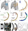
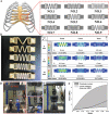
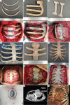
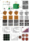
Three-dimensional printing (3DP) technology is suitable for manufacturing personalized orthopedic implants for reconstruction surgery. Compared with traditional titanium, polyether-ether-ketone (PEEK) is the ideal material for 3DP orthopedic implants due to its various advantages, including thermoplasticity, thermal stability, high chemical stability, and radiolucency suitable elastic modulus. However, it is challenging to develop a well-designed method and manufacturing technique to meet the clinical needs because it requires elaborate details and interplays with clinical work. Furthermore, establishing surgical standards for new implants requires many clinical cases and an accumulation of surgical experience. Thus, there are few case reports on using 3DP PEEK implants in clinical practice. Herein, we formed a team with a lot of engineers, scientists, and doctors and conducted a series of studies on the 3DP PEEK implants for chest wall reconstruction. First, the thoracic surgeons sort out the specific types of chest wall defects. Then, the engineers designed the shape of the implant and performed finite element analysis for every implant. To meet the clinical needs and mechanical requirements of implants, we developed a new fused deposition modeling technology to make personalized PEEK implants. Overall, the thoracic surgeons have used 114 personalized 3DP PEEK implants to reconstruct the chest wall defect and further established the surgical standards of the implants as part of the Chinese clinical guidelines. The surface modification technique and composite process are developed to overcome the new clinical problems of implant-related complications after surgery. Finally, the major challenges and possible solutions to translating 3DP PEEK implants into a mature and prevalent clinical product are discussed in the paper.
Keywords: Chest wall reconstruction; Fused deposition modeling; Polyether-ether-ketone; Three-dimensional printing.
Copyright: © 2022 Wang et al.
Conflict of interest statement
No conflicts of interest were reported by all authors.
Figures


Similar articles
-
Three-dimensional printed polyether-ether-ketone implant for extensive chest wall reconstruction: A case report.Thorac Cancer. 2020 Sep;11(9):2709-2712. doi: 10.1111/1759-7714.13560. Epub 2020 Jul 17. Thorac Cancer. 2020. PMID: 32677759 Free PMC article.
-
Three-Dimensional Printing PEEK Implant: A Novel Choice for the Reconstruction of Chest Wall Defect.Ann Thorac Surg. 2019 Mar;107(3):921-928. doi: 10.1016/j.athoracsur.2018.09.044. Epub 2018 Nov 4. Ann Thorac Surg. 2019. PMID: 30403979
-
Additively manufactured polyether ether ketone (PEEK) skull implant as an alternative to titanium mesh in cranioplasty.Int J Bioprint. 2022 Nov 4;9(1):634. doi: 10.18063/ijb.v9i1.634. eCollection 2023. Int J Bioprint. 2022. PMID: 36844244 Free PMC article.
-
Additive manufactured polyether-ether-ketone implants for orthopaedic applications: a narrative review.Biomater Transl. 2022 Jun 28;3(2):116-133. doi: 10.12336/biomatertransl.2022.02.001. eCollection 2022. Biomater Transl. 2022. PMID: 36105567 Free PMC article. Review.
-
Modification of polyether ether ketone for the repairing of bone defects.Biomed Mater. 2022 May 5;17(4). doi: 10.1088/1748-605X/ac65cd. Biomed Mater. 2022. PMID: 35395651 Review.
Cited by
-
3D-Printed Fast-Dissolving Oral Dosage Forms via Fused Deposition Modeling Based on Sugar Alcohol and Poly(Vinyl Alcohol)-Preparation, Drug Release Studies and In Vivo Oral Absorption.Pharmaceutics. 2023 Jan 24;15(2):395. doi: 10.3390/pharmaceutics15020395. Pharmaceutics. 2023. PMID: 36839717 Free PMC article.
-
Effect of Sterilization on the Dimensional and Mechanical Behavior of Polylactic Acid Pieces Produced by Fused Deposition Modeling.Polymers (Basel). 2023 Aug 6;15(15):3317. doi: 10.3390/polym15153317. Polymers (Basel). 2023. PMID: 37571211 Free PMC article.
-
Surface Treatment of Additively Manufactured Polyetheretherketone (PEEK) by Centrifugal Disc Finishing Process: Identification of the Key Parameters.Polymers (Basel). 2024 Aug 20;16(16):2348. doi: 10.3390/polym16162348. Polymers (Basel). 2024. PMID: 39204568 Free PMC article.
-
Outcomes following the excision of sarcoma and chest wall reconstruction using 3D printed implant.iScience. 2023 Dec 15;27(2):108757. doi: 10.1016/j.isci.2023.108757. eCollection 2024 Feb 16. iScience. 2023. PMID: 38313046 Free PMC article.
References
-
- Ambrosi A, Pumera M. 3D-printing technologies for electrochemical applications. Chem Soc Rev. 2016;45:2740–55. https://doi.org/10.1039/c5cs00714c. - PubMed
-
- Hu G, Kang J, Ng LW, et al. Functional inks and printing of two-dimensional materials. Chem Soc Rev. 2018;47:3265–300. https://doi.org/10.1039/c8cs00084k. - PubMed
-
- Layani M, Wang X, Magdassi S. Novel Materials for 3D Printing by Photopolymerization. Adv Mater. 2018;30:e1706344. https://doi.org/10.1002/adma.201706344. - PubMed
-
- Hirt L, Reiser A, Spolenak R, et al. Additive manufacturing of metal structures at the micrometer scale. Adv Mater. 2017;29:1604211. https://doi.org/10.1002/adma.201604211. - PubMed
-
- Liaw CY, Guvendiren M. Current and emerging applications of 3D printing in medicine. Biofabrication. 2017;9:024102. https://doi.org/10.1088/1758-5090/aa7279. - PubMed
Publication types
LinkOut - more resources
Full Text Sources
