

Theoretical and Experimental Assay of Shock Experienced by Yeast Cells during Laser Bioprinting
- PMID: 36077218
- PMCID: PMC9456252
- DOI: 10.3390/ijms23179823
Theoretical and Experimental Assay of Shock Experienced by Yeast Cells during Laser Bioprinting
Abstract
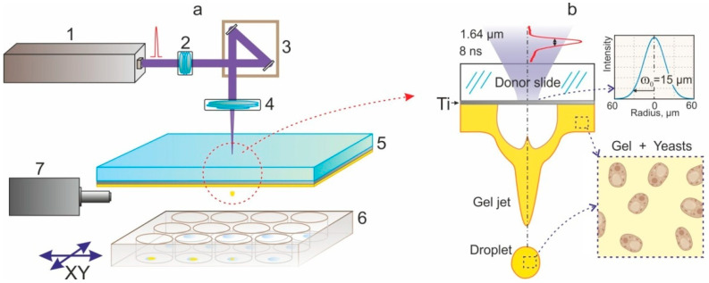
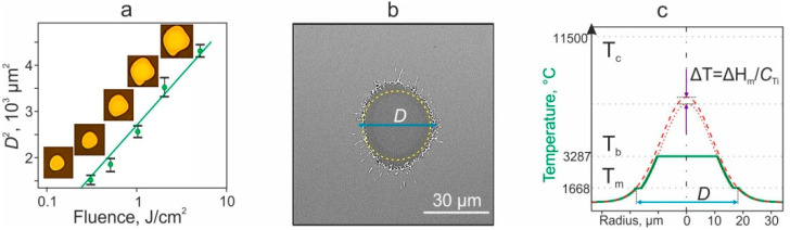
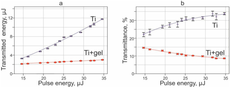
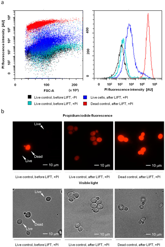
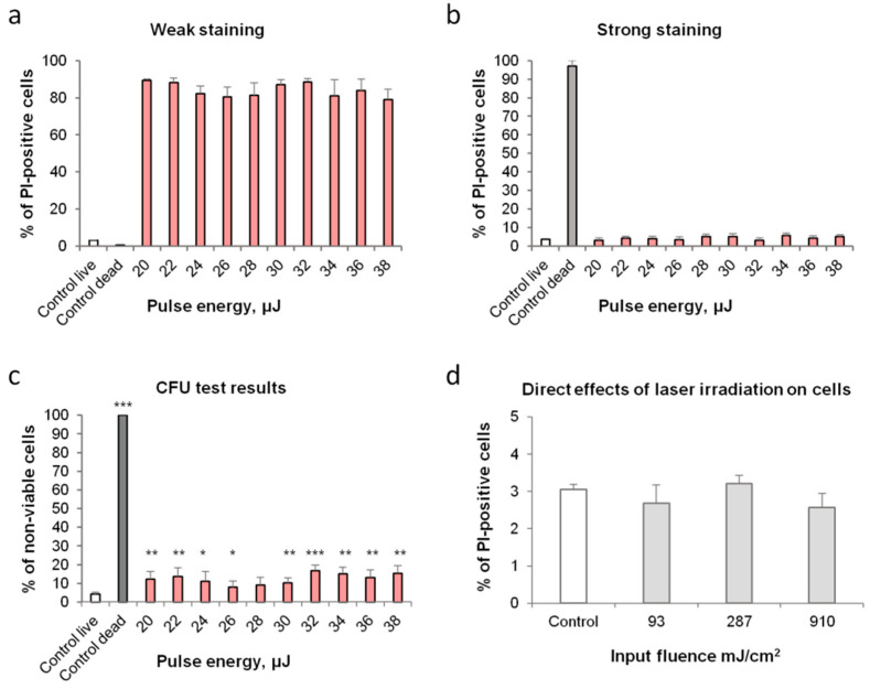
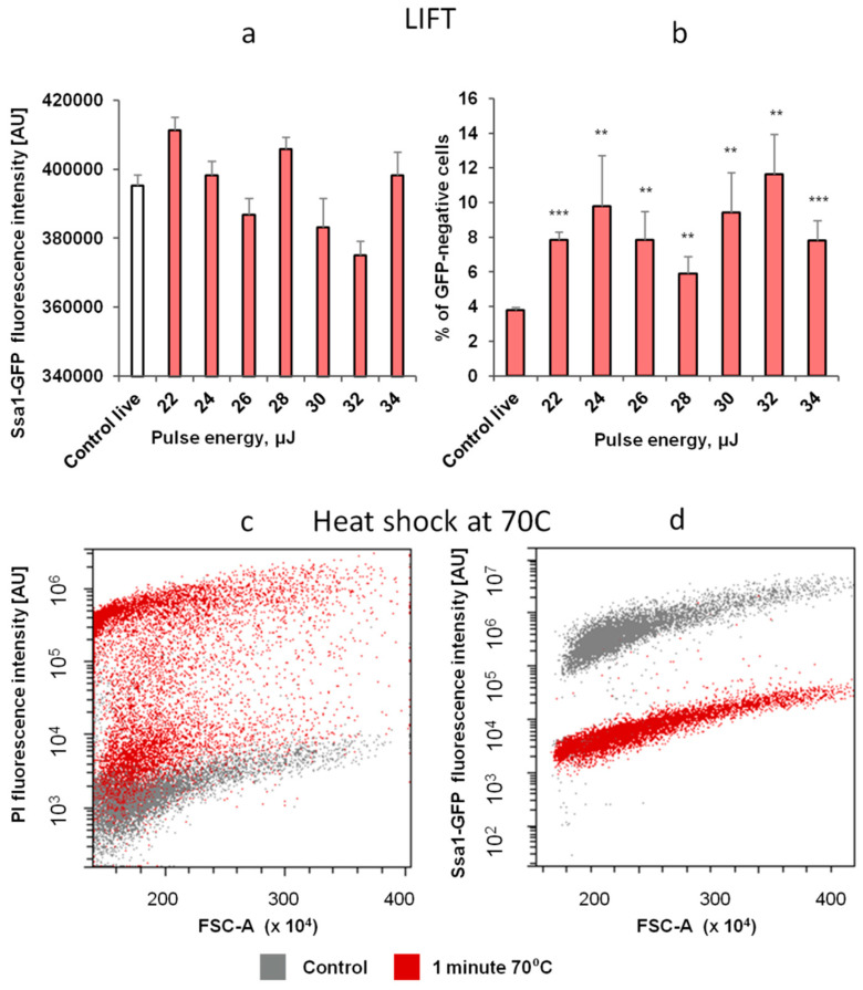
Laser-induced forward transfer (LIFT) is a useful technique for bioprinting using gel-embedded cells. However, little is known about the stresses experienced by cells during LIFT. This paper theoretically and experimentally explores the levels of laser pulse irradiation and pulsed heating experienced by yeast cells during LIFT. It has been found that only 5% of the cells in the gel layer adjacent to the absorbing Ti film should be significantly heated for fractions of microseconds, which was confirmed by the fact that a corresponding population of cells died during LIFT. This was accompanied by the near-complete dimming of intracellular green fluorescent protein, also observed in response to heat shock. It is shown that microorganisms in the gel layer experience laser irradiation with an energy density of ~0.1-6 J/cm2. This level of irradiation had no effect on yeast on its own. We conclude that in a wide range of laser fluences, bioprinting kills only a minority of the cell population. Importantly, we detected a previously unobserved change in membrane permeability in viable cells. Our data provide a wider perspective on the effects of LIFT-based bioprinting on living organisms and might provide new uses for the procedure based on its effects on cell permeability.
Keywords: cell death; laser bioprinting; laser-induced forward transfer (LIFT); membrane perturbation; yeast.
Conflict of interest statement
The authors declare no conflict of interest.
Figures


Similar articles
-
Fluorescence enhanced BA-LIFT for single cell detection and isolation.Biofabrication. 2020 Feb 26;12(2):025019. doi: 10.1088/1758-5090/ab6138. Biofabrication. 2020. PMID: 31829985
-
Laser-assisted bioprinting of microorganisms with hydrogel microdroplets: peculiarities of Ascomycota and Basidiomycota yeast transfer.World J Microbiol Biotechnol. 2022 Nov 28;39(1):29. doi: 10.1007/s11274-022-03478-z. World J Microbiol Biotechnol. 2022. PMID: 36437388
-
Study of gelatin as an effective energy absorbing layer for laser bioprinting.Biofabrication. 2017 Jun 9;9(2):024103. doi: 10.1088/1758-5090/aa74f2. Biofabrication. 2017. PMID: 28597844
-
Laser assisted cell printing.Curr Pharm Biotechnol. 2013;14(1):91-7. Curr Pharm Biotechnol. 2013. PMID: 23570054 Review.
-
Recent advances in bioprinting techniques: approaches, applications and future prospects.J Transl Med. 2016 Sep 20;14:271. doi: 10.1186/s12967-016-1028-0. J Transl Med. 2016. PMID: 27645770 Free PMC article. Review.
Cited by
-
Laser Bioprinting with Cell Spheroids: Accurate and Gentle.Micromachines (Basel). 2023 May 30;14(6):1152. doi: 10.3390/mi14061152. Micromachines (Basel). 2023. PMID: 37374737 Free PMC article.
-
Development and Prospective Applications of 3D Membranes as a Sensor for Monitoring and Inducing Tissue Regeneration.Membranes (Basel). 2023 Sep 18;13(9):802. doi: 10.3390/membranes13090802. Membranes (Basel). 2023. PMID: 37755224 Free PMC article. Review.
-
High-Affinity Plasma Membrane Ca2+ Channel Cch1 Modulates Adaptation to Sodium Dodecyl Sulfate-Triggered Rise in Cytosolic Ca2+ Concentration in Ogataea parapolymorpha.Int J Mol Sci. 2024 Oct 25;25(21):11450. doi: 10.3390/ijms252111450. Int J Mol Sci. 2024. PMID: 39519003 Free PMC article.
References
-
- Serra P., Piqué A. Laser-Induced Forward Transfer: Fundamentals and Applications. Adv. Mater. Technol. 2019;4:1800099. doi: 10.1002/admt.201800099. - DOI
-
- Adrian F.J., Bohandy J., Kim B.F., Jette A.N., Thompson P. A Study of the Mechanism of Metal Deposition by the Laser-induced Forward Transfer Process. J. Vac. Sci. Technol. B Microelectron. Process. Phenom. 1998;5:1490. doi: 10.1116/1.583661. - DOI
-
- Michael S., Sorg H., Peck C.T., Koch L., Deiwick A., Chichkov B., Vogt P.M., Reimers K. Tissue Engineered Skin Substitutes Created by Laser-Assisted Bioprinting Form Skin-Like Structures in the Dorsal Skin Fold Chamber in Mice. PLoS ONE. 2013;8:e57741. doi: 10.1371/journal.pone.0057741. - DOI - PMC - PubMed
-
- Saygili E., Dogan-Gurbuz A.A., Yesil-Celiktas O., Draz M.S. 3D Bioprinting: A Powerful Tool to Leverage Tissue Engineering and Microbial Systems. Bioprinting. 2020;18:e00071. doi: 10.1016/j.bprint.2019.e00071. - DOI
MeSH terms
Grants and funding
LinkOut - more resources
Full Text Sources
Molecular Biology Databases
