

Microbial fuel cells and their electrified biofilms
- PMID: 34729468
- PMCID: PMC8543385
- DOI: 10.1016/j.bioflm.2021.100057
Microbial fuel cells and their electrified biofilms
Abstract
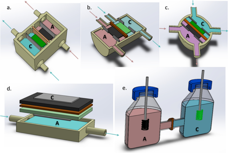
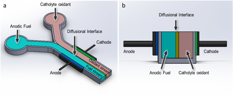
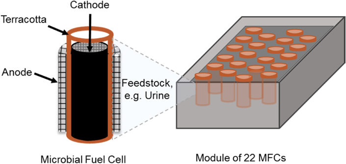
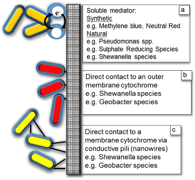
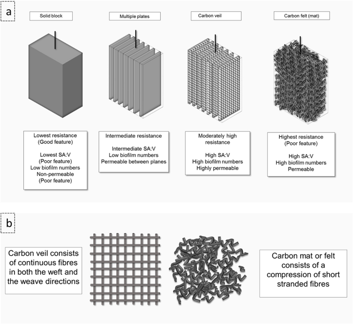
Bioelectrochemical systems (BES) represent a wide range of different biofilm-based bioreactors that includes microbial fuel cells (MFCs), microbial electrolysis cells (MECs) and microbial desalination cells (MDCs). The first described bioelectrical bioreactor is the Microbial Fuel Cell and with the exception of MDCs, it is the only type of BES that actually produces harvestable amounts of electricity, rather than requiring an electrical input to function. For these reasons, this review article, with previously unpublished supporting data, focusses primarily on MFCs. Of relevance is the architecture of these bioreactors, the type of membrane they employ (if any) for separating the chambers along with the size, as well as the geometry and material composition of the electrodes which support biofilms. Finally, the structure, properties and growth rate of the microbial biofilms colonising anodic electrodes, are of critical importance for rendering these devices, functional living 'engines' for a wide range of applications.
Keywords: Bioenergy; Electricity; Microbial fuel cell; Perfusion electrodes; Synchrony.
© 2021 Published by Elsevier B.V.
Conflict of interest statement
The author(s) declare no competing financial interests.
Figures
Similar articles
-
Depressing time: Waiting, melancholia, and the psychoanalytic practice of care.In: Kirtsoglou E, Simpson B, editors. The Time of Anthropology: Studies of Contemporary Chronopolitics. Abingdon: Routledge; 2020. Chapter 5. In: Kirtsoglou E, Simpson B, editors. The Time of Anthropology: Studies of Contemporary Chronopolitics. Abingdon: Routledge; 2020. Chapter 5. PMID: 36137063 Free Books & Documents. Review.
-
Qualitative evidence synthesis informing our understanding of people's perceptions and experiences of targeted digital communication.Cochrane Database Syst Rev. 2019 Oct 23;10(10):ED000141. doi: 10.1002/14651858.ED000141. Cochrane Database Syst Rev. 2019. PMID: 31643081 Free PMC article.
-
Comparison of Two Modern Survival Prediction Tools, SORG-MLA and METSSS, in Patients With Symptomatic Long-bone Metastases Who Underwent Local Treatment With Surgery Followed by Radiotherapy and With Radiotherapy Alone.Clin Orthop Relat Res. 2024 Dec 1;482(12):2193-2208. doi: 10.1097/CORR.0000000000003185. Epub 2024 Jul 23. Clin Orthop Relat Res. 2024. PMID: 39051924
-
Unlocking data: Decision-maker perspectives on cross-sectoral data sharing and linkage as part of a whole-systems approach to public health policy and practice.Public Health Res (Southampt). 2024 Nov 20:1-30. doi: 10.3310/KYTW2173. Online ahead of print. Public Health Res (Southampt). 2024. PMID: 39582242
-
Trends in Surgical and Nonsurgical Aesthetic Procedures: A 14-Year Analysis of the International Society of Aesthetic Plastic Surgery-ISAPS.Aesthetic Plast Surg. 2024 Oct;48(20):4217-4227. doi: 10.1007/s00266-024-04260-2. Epub 2024 Aug 5. Aesthetic Plast Surg. 2024. PMID: 39103642 Review.
Cited by
-
Recent Implementations of Hydrogel-Based Microbial Electrochemical Technologies (METs) in Sensing Applications.Sensors (Basel). 2023 Jan 6;23(2):641. doi: 10.3390/s23020641. Sensors (Basel). 2023. PMID: 36679438 Free PMC article. Review.
-
Lysozyme regulates the extracellular polymer of activated sludge and promotes the formation of electroactive biofilm.Bioprocess Biosyst Eng. 2022 Jun;45(6):1065-1074. doi: 10.1007/s00449-022-02727-7. Epub 2022 May 5. Bioprocess Biosyst Eng. 2022. PMID: 35511298
-
Polyaniline-Derived Nitrogen-Containing Carbon Nanostructures with Different Morphologies as Anode Modifier in Microbial Fuel Cells.Int J Mol Sci. 2022 Sep 23;23(19):11230. doi: 10.3390/ijms231911230. Int J Mol Sci. 2022. PMID: 36232531 Free PMC article.
-
Isolation and Characterisation of Electrogenic Bacteria from Mud Samples.Microorganisms. 2023 Mar 17;11(3):781. doi: 10.3390/microorganisms11030781. Microorganisms. 2023. PMID: 36985354 Free PMC article.
-
Engineered microbial consortia: strategies and applications.Microb Cell Fact. 2021 Nov 16;20(1):211. doi: 10.1186/s12934-021-01699-9. Microb Cell Fact. 2021. PMID: 34784924 Free PMC article. Review.
References
-
- Potter M.C. Electrical effects accompanying the decomposition of organic compounds. Proc R Soc B Biol Sci. 1911;84:260–276. doi: 10.1098/rspb.1911.0073. - DOI
-
- Qian F., He Z., Thelen M.P., Li Y. A microfluidic microbial fuel cell fabricated by soft lithography. Bioresour Technol. 2011;102:5836–5840. - PubMed
-
- Ieropoulos I., Greenman J., Melhuish C. Microbial fuel cells based on carbon veil electrodes: stack configuration and scalability. Int J Energy Res. 2008;32:1228–1240. doi: 10.1002/er. - DOI
-
- Greenman J., Ieropoulos I.A. Allometric scaling of microbial fuel cells and stacks: the lifeform case for scale-up. J Power Sources. 2017;356:365–370. doi: 10.1016/J.JPOWSOUR.2017.04.033. - DOI
LinkOut - more resources
Full Text Sources
