Engineering a Chemically Defined Hydrogel Bioink for Direct Bioprinting of Microvasculature
- PMID: 33332959
- PMCID: PMC7870577
- DOI: 10.1021/acs.biomac.0c00947
Engineering a Chemically Defined Hydrogel Bioink for Direct Bioprinting of Microvasculature
Abstract
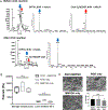
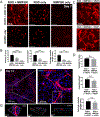
Vascularizing printed tissues is a critical challenge in bioprinting. While protein-based hydrogel bioinks have been successfully used to bioprint microvasculature, their compositions are ill-defined and subject to batch variation. Few studies have focused on engineering proangiogenic bioinks with defined properties to direct endogenous microvascular network formation after printing. Here, a peptide-functionalized alginate hydrogel bioink with defined mechanical, rheological, and biochemical properties is developed for direct bioprinting of microvascularized tissues. An integrin-binding peptide (RGD) and a vascular endothelial growth factor-mimetic peptide with a protease-sensitive linker are conjugated onto a biodegradable alginate to synergistically promote vascular morphogenesis and capillary-scale endothelial tube formation. Partial ionic crosslinking before printing converts the otherwise unprintable hydrogel into a viscoelastic bioink with excellent printability and cytocompatibility. We use the bioink to fabricate a compartmentalized vascularized tissue construct, wherein we observe pericyte-endothelial cell colocalization and angiogenic sprouting across a tissue interface, accompanied by deposition of fibronectin and collagen in vascular and tissue components, respectively. This study provides a tunable and translational "off-the-shelf" hydrogel bioink with defined composition for vascularized bioprinting.
Conflict of interest statement
The authors declare no conflict of interest.
Figures


Similar articles
-
Multilayered and heterogeneous hydrogel construct printing system with crosslinking aerosol.Biofabrication. 2021 Sep 23;13(4). doi: 10.1088/1758-5090/ac25ca. Biofabrication. 2021. PMID: 34507302
-
3D bioprinting of molecularly engineered PEG-based hydrogels utilizing gelatin fragments.Biofabrication. 2021 Aug 5;13(4). doi: 10.1088/1758-5090/ac0ff0. Biofabrication. 2021. PMID: 34192670
-
Alginate-Based Bioinks for 3D Bioprinting and Fabrication of Anatomically Accurate Bone Grafts.Tissue Eng Part A. 2021 Sep;27(17-18):1168-1181. doi: 10.1089/ten.TEA.2020.0305. Epub 2021 Feb 26. Tissue Eng Part A. 2021. PMID: 33218292 Free PMC article.
-
Advanced Strategies for 3D Bioprinting of Tissue and Organ Analogs Using Alginate Hydrogel Bioinks.Mar Drugs. 2021 Dec 15;19(12):708. doi: 10.3390/md19120708. Mar Drugs. 2021. PMID: 34940707 Free PMC article. Review.
-
Exploiting the role of nanoparticles for use in hydrogel-based bioprinting applications: concept, design, and recent advances.Biomater Sci. 2021 Sep 28;9(19):6337-6354. doi: 10.1039/d1bm00605c. Biomater Sci. 2021. PMID: 34397056 Review.
Cited by
-
Photocuring 3D printing technology as an advanced tool for promoting angiogenesis in hypoxia-related diseases.J Tissue Eng. 2024 Sep 24;15:20417314241282476. doi: 10.1177/20417314241282476. eCollection 2024 Jan-Dec. J Tissue Eng. 2024. PMID: 39345255 Free PMC article. Review.
-
Recent Advances in Decellularized Matrix-Derived Materials for Bioink and 3D Bioprinting.Gels. 2023 Mar 3;9(3):195. doi: 10.3390/gels9030195. Gels. 2023. PMID: 36975644 Free PMC article. Review.
-
Bioprinted vascular tissue: Assessing functions from cellular, tissue to organ levels.Mater Today Bio. 2023 Oct 28;23:100846. doi: 10.1016/j.mtbio.2023.100846. eCollection 2023 Dec. Mater Today Bio. 2023. PMID: 37953757 Free PMC article. Review.
-
Spatial control of self-organizing vascular networks with programmable aptamer-tethered growth factor photopatterning.Mater Today Bio. 2023 Jan 20;19:100551. doi: 10.1016/j.mtbio.2023.100551. eCollection 2023 Apr. Mater Today Bio. 2023. PMID: 36747582 Free PMC article.
-
Emerging 3D bioprinting applications in plastic surgery.Biomater Res. 2023 Jan 3;27(1):1. doi: 10.1186/s40824-022-00338-7. Biomater Res. 2023. PMID: 36597149 Free PMC article. Review.
References
-
- Datta P; Ayan B; Ozbolat IT, Bioprinting for vascular and vascularized tissue biofabrication. Acta Biomater. 2017, 51, 1–20. - PubMed
-
- Ozbolat IT, Bioprinting scale-up tissue and organ constructs for transplantation. Trends Biotechnol. 2015, 33, (7), 395–400. - PubMed
-
- Murphy SV; Atala A, 3D bioprinting of tissues and organs. Nat. Biotechnol 2014, 32, (8), 773–85. - PubMed
-
- Segal SS, Regulation of blood flow in the microcirculation. Microcirculation 2005, 12, (1), 33–45. - PubMed
Publication types
MeSH terms
Substances
Grants and funding
LinkOut - more resources
Full Text Sources

