

An introduction to cryo-FIB-SEM cross-sectioning of frozen, hydrated Life Science samples
- PMID: 32737879
- PMCID: PMC7891420
- DOI: 10.1111/jmi.12951
An introduction to cryo-FIB-SEM cross-sectioning of frozen, hydrated Life Science samples
Abstract
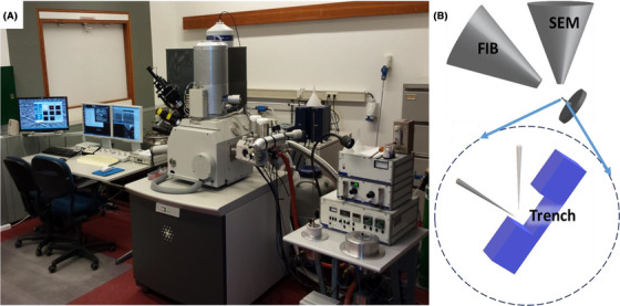
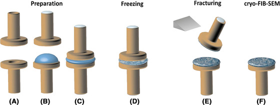
The introduction of cryo-techniques to the focused ion-beam scanning electron microscope (FIB-SEM) has brought new opportunities to study frozen, hydrated samples from the field of Life Sciences. Cryo-techniques have long been employed in electron microscopy. Thin electron transparent sections are produced by cryo-ultramicrotomy for observation in a cryo-transmission electron microscope (TEM). Cryo-TEM is presently reaching the imaging of macromolecular structures. In parallel, cryo-fractured surfaces from bulk materials have been investigated by cryo-SEM. Both cryo-TEM and cryo-SEM have provided a wealth of information, despite being 2D techniques. Cryo-TEM tomography does provide 3D information, but the thickness of the volume has a maximum of 200-300 nm, which limits the 3D information within the context of specific structures. FIB-milling enables imaging additional planes by creating cross-sections (e.g. cross-sectioning or site-specific X-sectioning) perpendicular to the cryo-fracture surface, thus adding a third imaging dimension to the cryo-SEM. This paper discusses how to produce suitable cryo-FIB-SEM cross-section results from frozen, hydrated Life Science samples with emphasis on 'common knowledge' and reoccurring observations. LAY DESCRIPTION: Life Sciences studies life down to the smallest details. Visualising the smallest details requires electron microscopy, which utilises high-vacuum chambers. One method to maintain the integrity of Life Sciences samples under vacuum conditions is freezing. Frozen samples can remain in a suspended state. As a result, research can be carried out without having to change the chemistry or internal physical structure of the samples. Two types of electron microscopes equipped with cryo-sample handling facilities are used to investigate samples: The scanning electron microscope (SEM) which investigates surfaces and the transmission electron microscope (TEM) which investigates thin electron transparent sections (called lamellae). A third method of investigation combines a SEM with a focused ion beam (FIB) to form a cryo-FIB-SEM, which is the basis of this paper. The electron beam images the cryo-sample surface while the ion beam mills into the surface to expose the interior of the sample. The latter is called cross-sectioning and the result provides a way of investigating the 3rd dimension of the sample. This paper looks at the making of cross-sections in this manner originating from knowledge and experience gained with this technique over many years. This information is meant for newcomers, and experienced researchers in cryo-microscopy alike.
Keywords: Cross-section; FIB-SEM; cryo-FIB-SEM; cryo-fracture; serial-sectioning; site-specific X-sectioning; vitrification.
© 2020 The Authors. Journal of Microscopy published by John Wiley & Sons Ltd on behalf of Royal Microscopical Society.
Figures


Similar articles
-
Cryo-FIB preparation of whole cells and tissue for cryo-TEM: use of high-pressure frozen specimens in tubes and planchets.J Microsc. 2021 Feb;281(2):125-137. doi: 10.1111/jmi.12943. Epub 2020 Jul 28. J Microsc. 2021. PMID: 32691851 Free PMC article.
-
Advanced cryo-tomography workflow developments - correlative microscopy, milling automation and cryo-lift-out.J Microsc. 2021 Feb;281(2):112-124. doi: 10.1111/jmi.12939. Epub 2020 Jul 2. J Microsc. 2021. PMID: 32557536
-
Cryo-focused-ion-beam applications in structural biology.Arch Biochem Biophys. 2015 Sep 1;581:122-30. doi: 10.1016/j.abb.2015.02.009. Epub 2015 Feb 20. Arch Biochem Biophys. 2015. PMID: 25703192 Review.
-
Practical workflow for cryo focused-ion-beam milling of tissues and cells for cryo-TEM tomography.J Struct Biol. 2014 Jan;185(1):32-41. doi: 10.1016/j.jsb.2013.10.019. Epub 2013 Nov 6. J Struct Biol. 2014. PMID: 24211822 Free PMC article.
-
The application and development of electron microscopy for three-dimensional reconstruction in life science: a review.Cell Tissue Res. 2024 Apr;396(1):1-18. doi: 10.1007/s00441-024-03878-7. Epub 2024 Feb 28. Cell Tissue Res. 2024. PMID: 38416172 Review.
Cited by
-
Interactions between interfaces dictate stimuli-responsive emulsion behaviour.Nat Commun. 2023 Oct 23;14(1):6723. doi: 10.1038/s41467-023-42379-z. Nat Commun. 2023. PMID: 37872193 Free PMC article.
-
Plasma-Derived Fibrin Hydrogels Containing Graphene Oxide for Infections Treatment.ACS Mater Lett. 2023 Mar 23;5(4):1245-1255. doi: 10.1021/acsmaterialslett.2c01044. eCollection 2023 Apr 3. ACS Mater Lett. 2023. PMID: 38323142 Free PMC article.
-
Polymorphism in peptide self-assembly visualized.Proc Natl Acad Sci U S A. 2022 Feb 8;119(6):e2123197119. doi: 10.1073/pnas.2123197119. Proc Natl Acad Sci U S A. 2022. PMID: 35105818 Free PMC article. No abstract available.
-
Neutral Dissociation of Pyridine Evoked by Irradiation of Ionized Atomic and Molecular Hydrogen Beams.Int J Mol Sci. 2021 Dec 24;23(1):205. doi: 10.3390/ijms23010205. Int J Mol Sci. 2021. PMID: 35008633 Free PMC article.
-
Cryo-FIB preparation of whole cells and tissue for cryo-TEM: use of high-pressure frozen specimens in tubes and planchets.J Microsc. 2021 Feb;281(2):125-137. doi: 10.1111/jmi.12943. Epub 2020 Jul 28. J Microsc. 2021. PMID: 32691851 Free PMC article.
References
-
- Ali, M.Y. & Hung, N.P. (2006) Surface roughness of sputtered silicon. II. Model verification. Mater. Manufact. Process. 16, 315–329.
-
- Baker, M.J. , Denton, T.T. & Herr, C. (2013) An explanation for why it is difficult to form slush nitrogen from liquid nitrogen used previously for this purpose. Cryobiol. 66, 43–46. - PubMed
-
- Ball, P. (2008) Water as an active constituent in cell biology. Chem. Rev. 108, 74–108. - PubMed
MeSH terms
LinkOut - more resources
Full Text Sources
Research Materials
