. 2020 Jan 20:9:e51131.
doi: 10.7554/eLife.51131.

The kinesin-5 tail domain directly modulates the mechanochemical cycle of the motor domain for anti-parallel microtubule sliding

Affiliations

The kinesin-5 tail domain directly modulates the mechanochemical cycle of the motor domain for anti-parallel microtubule sliding

Tatyana Bodrug et al. Elife. .

Abstract

Kinesin-5 motors organize mitotic spindles by sliding apart microtubules. They are homotetramers with dimeric motor and tail domains at both ends of a bipolar minifilament. Here, we describe a regulatory mechanism involving direct binding between tail and motor domains and its fundamental role in microtubule sliding. Kinesin-5 tails decrease microtubule-stimulated ATP-hydrolysis by specifically engaging motor domains in the nucleotide-free or ADP states. Cryo-EM reveals that tail binding stabilizes an open motor domain ATP-active site. Full-length motors undergo slow motility and cluster together along microtubules, while tail-deleted motors exhibit rapid motility without clustering. The tail is critical for motors to zipper together two microtubules by generating substantial sliding forces. The tail is essential for mitotic spindle localization, which becomes severely reduced in tail-deleted motors. Our studies suggest a revised microtubule-sliding model, in which kinesin-5 tails stabilize motor domains in the microtubule-bound state by slowing ATP-binding, resulting in high-force production at both homotetramer ends.

Keywords: D. melanogaster; Microtubule; cell biology; human; kinesin-5; mitosis; mitotic spindle; molecular biophysics; motor protein; sliding; structural biology.


Conflict of interest statement

TB, EW, SN, AT, AA, IG, JM, GD, SI, PG, LG, RM, CS, RM, JS, SR, SF, JA No competing interests declared

Figures
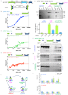
Figure 1.
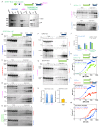
Figure 1.. The kinesin-5 tail domain inhibits the motor domain MT-stimulated ATPase activity through stabilization of the MT bound nucleotide-free state.
(A) Top, domain organization for the kinesin-5 motors, Dm KLP61F and Hs FL-Eg5 consisting of conserved N-terminal motor domain, central BASS domain and C-terminal tail domain. Bottom, homotetrameric organization of kinesin-5. (B) Steady-state MT-stimulated ATP hydrolysis for KLP61F motor. (N = 2) (C) Steady state MT stimulated ATP hydrolysis for equimolar KLP61F motor + tail constructs. (N = 2) (D) Steady state MT stimulated ATP hydrolysis for KLP61F motor-tail fusion. (N = 2) (E) Affinity co-purification of the KLP61F motor using the KLP61F tail-StrepII trapping one of three nucleotide states conditions. Top panel, SDS-PAGE for each condition: 5 μmol motor + tail mixture is loaded onto Streptactin XT resin (Load), flow-through fraction (FL) and biotin elution fraction (elute) are shown. Left lanes, incubation of motor + tail with non-hydrolysable ATP-analog, 2 mM AMPPNP. Center lanes, incubation of motor + tail with 2 mM ADP. Right lanes, incubation of motor + tail in the presence of 2 U Apyrase resulting in a nucleotide free state. Bottom panel, quantitative densitometry reveals the molar ratios of motor to tail in the elution fractions at 25 mM KCl (yellow column) and 75 mM KCl (blue columns) buffer conditions (N = 3, n = 6 for each column). (F) MT co-sedimentation assays of the KLP61F motor (motor) and tail domain (tail) with MTs (MT) in the presence of non-hydrolysable analog, 2 mM AMPPNP at 25 mM KCl. Co-sedimentation was carried out with MTs for 0.01, 0.025, 0.05, 0.1,0.25 μmol motor and tail mixture at 25 mM KCl conditions, and in the absence of MTs (-MT) control. Additional data are shown in Figure 1—figure supplement 1B. (G) MT co-sedimentation assays of the KLP61F motor (motor) and tail domain (tail) with MTs (MT) in the presence of 2 mM ADP at 25 mM KCl. Co-sedimentation was carried out with MTs for 0.01, 0.025, 0.05, 0.1,0.25 μmol motor and tail mixture at 25 mM KCl condition and in the absence of MTs (-MT) control. Additional data are shown in Figure 1—figure supplement 1D. (H) MT co-sedimentation assays of the KLP61F motor (motor) and tail domain (tail) with MTs (MT) in the nucleotide-free state, achieved by adding 10 U of Apyrase. Co-sedimentation was carried out with MTs for 0.01, 0.025, 0.05, 0.1,0.25 μmol motor and tail mixture at 25 mM KCl conditions and in the absence of MTs (-MT) control. Detailed and additional data are shown in Figure 1—figure supplement 1E. (I) Molar ratios of motor to tubulin monomer (blue) and tail to tubulin dimer (green) measured using quantitative densitometry (Materials and methods). The motor-to-tubulin ratios observed at 75 mM KCl are roughly 0.5 and the amount of tail bound to the motor increases in the ADP and Nucleotide-free states increases in the 25 mM KCl compared to the 75 mM KCl conditions. The amount of tail bound to motor remain low in the AMPPNP and ADP.AlF4 states compared to the ADP and nucleotide-free states. (J) Summary of data presented resulting in a model for motor (green) and tail (blue) domain affinities and MT (blue and pink) binding capacities in four nucleotide states during the ATP hydrolysis cycle.
Figure 1—figure supplement 1.
Figure 1—figure supplement 1.. The kinesin-5 tail domain inhibits motor domain MT-stimulated ATPase activity through stabilization of ADP-bound and nucleotide-free state.
(A) Affinity co-purification of the KLP61F motor using the tail-StrepII construct in solution in the presence of three nucleotide states at 15 μmol mixture of motor+ tail-StrepII, which is three-fold higher than data shown in Figure 1E. (B) MT co-sedimentation assays of the KLP61F motor (motor) and tail domain (tail) at 0.01, 0.25, 0.05,0.1,0.25 μmol with MTs (tubulin) in the presence of non-hydrolysable analog, 2 mM AMPPNP separated into pellet (left) and supernatant (right) fractions at 75 mM KCl (top panel) and 25 mM KCl (bottom panel). (C) MT co-sedimentation assays of the KLP61F motor (motor) and tail domain (tail) at 0.01, 0.25, 0.05,0.1,0.25 μmol with MTs (tubulin) in the presence of non-hydrolysable analog, 2 mM ADP.AlF4, mimicking the ADP.Pi state separated into pellet (left) and supernatant (right) fractions at 75 mM KCl (top panel) and 25 mM KCl (bottom panel). (D) MT co-sedimentation assays of the KLP61F motor (motor) and tail domain (tail) at 0.01, 0.25, 0.05,0.1,0.25 μmol with MTs (tubulin) in the presence of the 2 mM ADP separated into pellet (left) and supernatant (right) fractions at 75 mM KCl (top panel) and 25 mM KCl (bottom panel). (E) MT co-sedimentation assays of the KLP61F motor (motor) and tail domain (tail) at 0.01, 0.25, 0.05,0.1,0.25 μmol with MTs (tubulin) in the nucleotide-free state, formed by adding 10 U of Apyrase and were separated into pellet (left) and supernatant (right) fractions at 75 mM KCl (top panel) and 25 mM KCl (bottom panel). (F) MT co-sedimentation assays of the KLP61F tail domain (tail) with MTs (tubulin) in the presence of 2 mM ADP at 75 mM KCl (top panel) and 25 mM KCl (lower panel). (G) MT co-sedimentation assays of the KLP61F motor domain (motor) with MTs (tubulin) in the presence of ADP at 75 mM KCl (top panel) and 25 mM KCl (lower panel). (H) The measured motor to tubulin (-tail) and tail to tubulin (-motor) molar ratios calculated using densitometry of SDS-PAGE data revealing thatthey saturate at ~1.0 and 0.5 per tubulin dimer, respectively. (I) Top panel, MT co-sedimentation of the human Eg5 motor domain (Eg5 motor) and tail domain (Eg5 tail) at 0.01, 0.025, 0.05, 0.1,0.25, 0.5 μmol mixture with MTs (tubulin) in the presence of 2 mM ADP. Note, the Eg5 tail domain shows a minor degradation form which also behaves in a similar manner to the tail construct (marked by *tail). Bottom panel, MT co-sedimentation assays of the human Eg5 motor domain (Eg5 motor) and tail domain (Eg5 tail) at 0.01, 0.025, 0.05, 0.1,0.25, 0.5 μmol mixtures with MTs (tubulin) with MTs (tubulin) in the presence of 2 mM AMPPNP. MT bound Pellet fraction (left) and soluble supernatant (right) are shown. Note, in the AMPPNP state the motor binds tightly while the tail is not found in the Pellet fraction. (J) Left panel, quantitative densitometry of the molar ratios of Eg5 motor/tubulin (blue) and tail/tubulin (green). These data show that the ratios are similar to the KLP61F experiments with lower binding stoichiometry in the AMPPNP state than the nucleotide-free and ADP states. (K) Top panel, schemes for Eg5 motor and tail constructs. Bottom panel, Steady state ATP hydrolysis for Eg5 motor (blue) and equimolar Eg5-motor + tail constructs (green) with increasing MT concentrations at 20 mM KCl condition (Table 1). (L) Top panel, schemes for Eg5 motor and Eg5-motor-tail fusion constructs. Bottom panel, steady state ATP hydrolysis for Eg5 motor (blue) and Eg5-motor-tail fusion constructs (red) with increasing MT concentrations at 20 mM KCl condition. Note the similarity of this data to the KLP61F data for a similar construct in Figure 1D. (Table 1). (M) Top panel, schemes for Eg5 motor and Eg5-motor-tail fusion constructs. Bottom panel, steady state ATP hydrolysis for Eg5 motor (blue) and Eg5-motor-tail fusion constructs (red) with increasing MT concentrations at 50 mM K-Acetate condition. Note the less severe decrease in ATPase in the Eg5.
Figure 2.
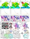
Figure 2.. Cryo-EM reveals the kinesin-5 tail engages the motor domain in the nucleotide-free state and stabilizes an open ATP active site.
(A-C) (A) Side view of 4.0 Å cryo-EM structure of Klp61F motor domain decorated MT unit in the AMPPNP state. A single kinesin motor-bound αβ-tubulin unit is shown. The segmented motor domain (yellow) and α-tubulin (cyan) and β-tubulin (green) densities are sown. (B) De novo built KLP61F motor domain model in the AMPPNP state (red) displayed within the motor domain density. The αβ-tubulin dimer model fitted into the αβ-tubulin density (green and cyan). (C) Top end view of the kinesin-5 motor density map with the MT density computationally removed. (D-F) (D) Side view of 4.0 Å cryo-EM structure of Klp61F motor and tail domains decorated onto MTs in the nucleotide-free state obtained using well-established and refined with new strategies (Figure 2—figure supplement 1A–C; see Materials and methods). The kinesin-motor + tail bound to a single αβ-tubulin unit is shown. Segmentation of the motor domain (yellow), tail domain is shown (blue), α-tubulin (cyan) and β-tubulin (green). (E) De novo built Klp61F motor domain model in the nucleotide-free state (orange) displayed within the motor domain density and the tail density (dark blue). The αβ-tubulin dimer fitted into the αβ-tubulin density (green and cyan). (F) Top-end view of the docked kinesin-5 motor and tail density with the MT density computationally removed. (G) Conformational transition of Klp61F motor domain from nucleotide-free (light gray) to AMPPNP (dark gray). The elements that undergo the most change in colors: α6 (blue), α2 (yellow), p-loop (green) and α0 helix (red). (I-J) Two views of the Klp61F AMPPNP and nucleotide-free motor domain models describing the movements of motor with N-terminal subdomain (deep blue, nucleotide-free (nuc.-free); light blue, AMPPNP) and Upper subdomain (deep pink, nucleotide-free; light pink, AMPPNP) around the α4-helix, L11 switch II (swII) MT bound subdomain (deep red, nucleotide-free; light red, AMPPNP). The switch I (swI) changes conformation in response to ATP binding. The N-terminal subdomain rotation leads to a 20° rotation of the α0-helix closer to the MT surface in the AMPPNP state. The tail binds the α0-helix in the nucleotide-free state. H) Side-view of the Klp61F motor domain maps in AMPPNP (red) compared to the nucleotide-free state model (orange) docked into the nucleotide free-state motor density with the tail density shown in blue.
Figure 2—figure supplement 1.
Figure 2—figure supplement 1.. Cryo-EM reveals the kinesin-5 tail domain engages the motor domain directly through the α0-helix and stabilizes an open ATP active site.
(A) Top panel (I): Colores view of the Klp61F motor MT AMPPNP map, colored based on resolution scale. Bottom Panel (II): A gold standard Fourier Shell correlation (FSC) curve for the MT-decorated Klp61F motor -AMPPNP state revealing an overall resolution of 4.4 Å. (B) Top panel (I): Colores view of the Klp61F motor + tail nucleotide-free MT decorated map colored based on resolution scale. Note the small size of the tail region. Bottom Panel (II); A gold standard Fourier Shell correlation (FSC) curve for the MT decorated Klp61F motor nucleotide-free map state revealing an overall resolution of 4.4 Å. (C) Top panel (I): Colores view of the Klp61F motor + tail nucleotide-free MT decorated map after MT-patch refinement (see Materials and methods). Note the increased size of the tail region but its low 8 Å resolution. The motor density resolution improved through the refinement procedure. Bottom Panel (II); A gold standard Fourier Shell correlation (FSC) curve for the MT-decorated Klp61F motor and tail in the nucleotide-free state revealing an overall resolution of 4.0 Å. (D) Close-up views of the motor domain active site in the AMPPNP state (left), nucleotide-free state (middle) and both states overlaid (overlay, right) with nucleotide-free state elements in faded colors. These views highligh switch II (swII; red), switch I loop (swI; pink) and the α0 helix hairpin(α0; blue). The right (overlay) panel shows the direction of displacement (in Å) between the AMPPNP and nucleotide free states. (E) Class averages of the Klp61F motor AMPPNP decorated MTs (AMPPNP top), and the Klp61F motor + tail nucleotide-free state decorated MTs (Nucleotide-free bottom). Right panels, top, a single AMPPNP motor-decorated MT, compared to nucleotide-free motor + tail decorated MT density is extracted and magnified. These reveal the general conformational changes of the motor domain and average density for the tail around the single binding site on the backside of the motor domain. (F) An overlay of the kinesin-5 motor, three subdomains highlighted, nucleotide-free state model to the kinesin-1 ATP-like state in faded highlighted subdomains revealing the conformational change in the α0 helix in kinesin-5 compared to the kinesin-1 ATP state. Loops L6 and L8 are seen at unique conformations compared to kinesin-1 and are labeled with black arrows. (G) An overlay of the kinesin-5 subdomain nucleotide-free model to the kinesin-1 nucleotide-free state model revealing the nearly identical conformation of α0 helix. Loops L6 and L8 are seen at a unique conformation compared to kinesin-1 and are labeled with black arrows. (H) View of the raw kinesin-5 motor tail nucleotide free map after patch refinement (as seen in panel C) with the segmentation for the map shown in the middle motor domain. Motor domain is shown in yellow; tail domain is shown in blue while α and β-tubulin are shown in cyan and green, respectively.
Figure 3.
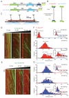
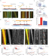
Figure 3.. The kinesin-5 tail domain decreases velocity for homotetrameric motors along MTs.
(A) Human Eg5 constructs used in reconstitution studies. Top panel, domain organization of FL-Eg5-GFP. Second panel, domain organization of Eg5-Δtail-GFP with its tail domain deleted (residues 920–1058) with the C-termini fused to monomeric superfolder GFP (msf-GFP). (B) The homotetrameric Eg5 organizations for the two constructs FL-Eg5-GFP and Eg5-Δtail-GFP, as described previously (Acar et al., 2013). (C) Scheme for TIRF microscopy of Eg5 motors (green) undergoing motility along single surface anchored AlexaF-633 and biotin labeled MTs via neutravidin-biotin attachment (red). (D) Kymographs of FL-Eg5-GFP motor motility along MTs in 25, 50 and 100 mM KCl pH 7.5 condition. Kymographs in dual color showing MTs (red) and GFP channels (green) are shown. Left panel, FL-Eg5-GFP motors undergo extremely slow motility at 25 mM KCl motor and their particle intensities are generally uniform. Middle panel, FL-Eg5 GFP undergoes motility with increased velocity and exhibits visual variation in particle intensity. Right panel, FL-Eg5-GFP motor show motility with higher velocity and exhibit bright and dim intensity particles at 100 mM KCl. Note FL-Eg5-GFP motors accumulate at MT plus-ends in 25 mM KCl; this plus-end residence decreases at 50 and 100 mM KCl. (E) Kymographs of Eg5-Δtail-GFP motility along anchored MTs at 25, 50 and 100 mM KCl pH 7.5 condition. Kymographs in dual color showing MTs (red) and GFP channels (green) are shown. Eg5-Δtail-GFP motors exhibit motility at similar velocities in all conditions. Note the homogeneity in motor intensities for Eg5-Δtail-GFP and its rapid motility at 25 mM KCl in contrast to the very slow motility of FL-Eg5-GFP. Motor intensities are uniform for Eg5-Δtail-GFP at 25 mM KCl and remain mostly homogeneously dim at 100 mM KCl. Note all Eg5-Δtail-GFP accumulate at MT plus-ends in a salt dependent manner. (F) Top panel, histogram for FL-Eg5-GFP motile particle velocity to frequency distribution reveals homogeneous and very slow velocity 25 mM KCl. Middle panel, histogram for FL-Eg5-GFP motor velocity to frequency distribution at 50 mM KCl reveals a 3-fold higher velocity than at 25 mM KCl. Bottom panel, histogram for velocity frequency bi-modal distribution for FL-Eg5-GFP at 100 mM KCl. Right inset panels show Eg5 fluorescence intensity distribution for motile particles at 25 and100 mM kCl. The fitted trend lines are shown in blue and averages are shown above each peak. These reveal that the motors are homogeneous homotetramers at 25 mM KCl, but cluster into dimers and tetramers of homotetramers at 100 mM KCl. Statistical t-tests are shown in Figure 3—figure supplement 1F. (G) Top panel, histogram for Eg5-Δtail-GFP motor motile particle velocity to frequency distribution (blue) at 25 mM KCl condition, revealing a three-folds faster than FL-Eg5-GFP at 25 mM KCl. Middle panel, histogram of velocity to frequency Eg5-Δtail-GFP motor particle distribution at 50 mM KCl revealing little change in velocity. Bottom panel, histogram of velocity to frequency distribution Eg5-Δtail-GFP motor particle revealing a bi-modal trend at 100 mM KCl. The fitted trend lines are shown in red and averages are shown above each peak. Inset panels at 25 and 100 mM KCl show that Eg5-Δtail-GFP motor fluorescence intensity distribution remain mostly as single homotetramers at 25 and 100 mM KCl. Statistical t-tests are shown in Figure 3—figure supplement 1G.
Figure 3—figure supplement 1.
Figure 3—figure supplement 1.. The tail domain decreases the velocity of homotetrameric kinesin-5 motors along MTs.
(A) Right panel, Size exclusion chromatography (SEC) for recombinant FL-Eg5-GFP (red) and SDS-PAGE lane for peak fraction. Left panel, SEC for recombinant Eg5-Δtail-GFP and SDS-PAGE lane for peak fraction. (B) Two color TIRF Fields for surface anchored MTs (red) with FL-Eg5-GFP (left) and Eg5-Δtail-GFP (right) revealing the highly robust motility activity in these imaging conditions at pH 7.5 at 25–100 mM KCl. (C) Frequency distribution for motile Fl-Eg5-GFP (red) and Eg5-Δtail-GFP (blue) motor run length at 50 and 100 mM KCl. These were fit with logarithmic decay trend linestrend lines to determine the average run length values. The run length analyses reveal that Fl-Eg5-GFP retains processive motility in both 50 and 100 mM KCl conditions, in contrast to Eg5-Δtail-GFP which is processive at 50 mM KCl but shows a two-fold decrease in run lengths at 100 mM KCl. (D) Additional example kymographs for Fl-Eg5-GFP as shown in Figure 3D. (E) Additional example kymographs for Eg5-Δtail-GFP as shown in Figure 3E. (F) Statistical t-tests comparing the data shown in Figure 3F–G.
Figure 4.
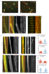
Figure 4.. The kinesin-5 tail is critical for the zippering of two sliding MTs via slow directional motility within the overlap zones.
(A) Left panel, scheme for TIRF microscopy reconstitution of MT sliding assays where FL-Eg5-GFP motors (green) recruit free MTs (orange) along single surface anchored AlexaF-633 and biotin labeled MTs via neutravidin-biotin (red). Right panel, scheme for TIRF microscopy MT sliding where Eg5-Δtail-GFP mediates crosslinking of the free-MT (orange) without zippering them along the AlexaF-633 and biotin labeled MTs via neutravidin-biotin (red). Their activity leads to scissoring motility. (B) Montages for two types of MT sliding events. Left panels, FL-Eg5-GFP mediates MT sliding. Right panels, Eg5-Δtail-GFP crosslinks MTs but does not zipper them along the anchored MT, leading to scissoring events. Additional examples in Figure 4—figure supplement 1B (C) The influence of ionic strength on FL-Eg5-GFP MT sliding activity. Top panel, FL-Eg5-GFP motor particle motility velocities (top panel) and free MT sliding velocity (lower panel). (D) The proportion of MT sliding and scissoring events in percentage of total observed for experiments at 20 and 200 nM Eg5-Δtail-GFP, respectively. The increase in Eg5-Δtail-GFP leads to higher proportion of MT sliding compared to scissoring events (N = 70–100 sliding/scissoring events for each condition). (E) Scheme for reconstitution of fluorescent Eg5 motor spiking in MT sliding assay with 20 nM FL-Eg5 (non-fluorescent, gray). 1 nM FL-Eg5-GFP or 1 nM Eg5-Δtail-GFP (green) were added to visualize single motors exhibit motility along the anchored MTs (red) and transition into the MT sliding zone with both free (yellow) and anchored MT (red). (F) Example kymographs of MT sliding spiking assays with 1 nM FL-Eg5-GFP in the presence of 20 nM FL-Eg5 (unlabeled). Three color kymographs are shown including the overlay (right panel), the free MT sliding (middle panel, yellow) being slide apart in the presence of single FL-Eg5-GFP motors (middle panel, green). Extreme right panels show a magnified views. Note the slow and directional motility of FL-Eg5-GFP motors. Additional examples in Figure 4—figure supplement 1C. (G) Example kymographs of MT sliding spiking assays with 1 nM Eg5-Δtail-GFP in the presence of 20 nM FL-Eg5 (unlabeled). Three color kymographs are shown including the overlay (right panel), the free MT sliding (middle panel, yellow) being slide apart in the presence of single Eg5-Δtail-GFP motors (middle panel, green). Extreme right panels show magnified view. Note FL-Eg5-GFP motors undergo bi-directional motility with stochastic switching (shown in red arrows) along either of the two anti-parallel MTs within sliding zones. Additional examples in Figure 4—figure supplement 1C. (H) Single motor track quantification of 1 nM FL-Eg5-GFP motor motility in the MT sliding zone (left, overlap) and along the anchored MT (right, single). Note FL-Eg5-GFP undergoes slow motility in general but its velocity decreases even further in the MT sliding zone. Average values reported in Table 5 (I) Single motor track quantification of 1 nM Eg5-Δtail-GFP motor motility in the MT sliding zone (left, overlap zone) and along the single anchored MT (right, single-MT). Note Eg5-Δtail-GFP undergoes rapid motility in both zones, but its motility switches direction (reversals marked by red arrow heads) particularly within the overlap region of the MT sliding zone. Average values reported in Table 5.
Figure 4—figure supplement 1.
Figure 4—figure supplement 1.. The kinesin-5 tail domain regulates the zippering of two sliding MTs via slow directional motility within the overlapping zones.
(A) Left side panels, wide field view of reconstituting 10–20 nM FL-Eg5-GFP mediated MT sliding events. Free MTs (yellow) can be seen recruited along anchored MTs (red) mediated by the FL-Eg5-GFP motors. Right panels, wide field image of reconstitutions of 10–20 nM Eg5-Δtail-GFP revealing a defect in MT sliding zone leading the free MT (yellow) to rotate around a single point, or scissor with respect to the anchored MT. (B) Left, time-lapse montage/kymograph reveal how Eg5 FL-GFP motors mediates crosslinking and then zippering of newly captured MT. Left panel montage in three colors showing the capture of the free MT (yellow) by Fl-Eg5-GFP motors (green) along the anchored MT, second panel, kymograph for event in three channels. Third panel, free MT channel. Fourth panel, FL-Eg5-GFP channels. The latter three panels show the boundaries of the free-MT sliding marked with broken lines. Right panels, Time-lapse montage/kymograph reveal how Eg5-Δtail-GFP motors mediates crosslinking and zippering defect leading to scissoring of the newly captured MT. Left panel, two color kymographs showing anchored MT (red) by Eg5-Δtail-GFP motors (green) along the anchored MT. (C) Additional Kymographs, similar to Figure 4F, for motor spiking into MT sliding assays. Left panels, 1 nM FL-Eg5-GFP motor (green) is spiked into MT sliding events formed by FL-Eg5 where free MT (yellow) is being slid along anchored MT (red). Note the unidirectional motility of the FL-EG5-GFP motors and their slow motility within the MT sliding zone. Right panels, 1 nM Eg5-Δtail-GFP are spiked into MT sliding events formed by FL-Eg5-GFP. Note the bi-directional motility of Eg5-Δtail-GFP within MT sliding zones. (D) Statistical t-tests comparing the raw motility data shown in Figure 4F–G.
Figure 5.
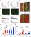
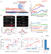
Figure 5.. Kinesin-5 tail is critical in generating pushing forces during MT sliding.
(A) Scheme for MT sliding and optical trapping to measure the MT sliding pushing forces. Hilyte 649 labeled and biotins labeled MTs (purple) were attached to glass surfaces via neutravidin-biotin. FL-Eg5-GFP motors (green) slide apart the Rhodamine-labeled MTs (red) while bound to a polystyrene bead (sphere) coated with kinesin-1 rigor mutant protein, which becomes locked into the optical trap to measure forces. (B) Example images of MT sliding events mediated by FL-Eg5-GFP (left) and Eg5-Δtail-GFP (right). Top, free MT shown in gray scale. Second, Eg5-GFP intensity in the overlap zone. Third, attached MT. The polystyrene bead can be seen attached to the free MT. Lower panel, fluorescence intensity for each of the channels above showing the identification of the overlap zone length and total GFP intensity above background. (C) Example optical trapping force profiles generated for sliding events by FL-Eg5-GFP (top) and Eg5-Δtail-GFP (bottom). Top panel, FL-Eg5-GFP MT sliding events generate and build up forces that then plateau (highlighted level). Lower panel, Eg5-Δtail-GFP MT sliding events generate very weak forces, which plateau at lower values. (D) Scaled comparison for overlap zone length (μm) plotted in relation to the overall GFP intensity for each sliding event. FL-Eg5-GFP is shown in red while Eg5-Δtail-GFP is shown in blue. Note there is generally little discernible statistical difference between the slopes of these comparisons. (E) Scaled comparison of the plateau forces generated (pN) in relation to the size of the overlap zone for each MT sliding event. FL-Eg5-GFP is shown in red while Eg5-Δtail-GFP is shown in blue. Note the slope of the FL-Eg5-GFP force to length comparison is steeper than the Eg5-Δtail-GFP force to length comparison (F) Forces generated per μm of overlap length representing the slope of linear comparison in E.
Figure 6.
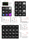
Figure 6.. Deletion of the kinesin-5 tail domain disrupts localization of the motor to the mitotic spindle in metaphase and anaphase.
(A) Western blot for mCherry (mCh, green) and GAPDH (red) indicating the expression of FL-Eg5-mCherry (FL Eg5-mCh, green) and Eg5-Δtail-mCherry (Eg5-Δtail-mCh, green) in HeLa cells. Results are representative of three independent experiments. (B) Localization of mCh, FL-Eg5-mCh, and Eg5-Δtail-mCh in HeLa cells arrested in metaphase via treatment with MG-132. FL-Eg5-mCh localized to spindle MTs. Tail deletion disrupted localization, and Eg5-Δtail-mCh signal was distributed between spindle MTs and the cytoplasm. Scale bar 10 μm. Images are representative of three independent experiments. (C) Left panel, mCh fluorescence intensities of single cells used for quantification of localization to spindle MTs (n = 13–29 cells per transfection condition, three independent experiments). Right panel, the ratio of mCh fluorescence signal on the spindle to signal in the cytoplasm was significantly lower in fixed metaphase cells expressing Eg5-Δtail-mCh compared to FL-Eg5-mCh, indicating reduced localization of Eg5-Δtail-mCh to spindle MTs (n = 13–29 cells per transfection condition, three independent experiments, p values from ANOVA with Tukey’s post hoc test). (D) Treatment of live HeLa cells expressing Eg5-mCh constructs and GFP-Tubulin with the Eg5 rigor inhibitor BRD-9876 resulted in a rapid (<1 min) increase in FL-Eg5-mCh signal on the spindle. Inhibitor treatment increased, but did not fully rescue, localization of Eg5-Δtail-mCh to the spindle. Scale bar 10 μm. Images are representative of three independent experiments. (E) The ratio of mCh fluorescence signal on the spindle to signal in the cytoplasm rapidly increased after treatment with BRD-9876 in cells expressing FL-Eg5-mCh or Eg5-Δtail-mCh. The spindle-to-cytoplasm intensity ratio of Eg5-Δtail-mCh expressing cells never reached that of cells expressing FL-Eg5-mCh, indicating only partial rescue of motor localization with rigor inhibitor treatment. BRD-9876 treatment did not alter the ratio of mCh control cells (n = 7–13 cells per transfection condition, three independent experiments). (F) Deletion of the tail domain disrupted localization of Eg5 to the spindle in anaphase. Paired rows of images demonstrate the localization of FL-Eg5-mCh and Eg5-Δtail-mCh as HeLa cells expressing GFP-tubulin transitioned from metaphase to anaphase. FL-Eg5-mCh signal was observed at the spindle throughout the metaphase to anaphase transition and the motor localized to the midzone after anaphase onset (see 4–6 min panels). Increased cytoplasmic and reduced spindle signal was observed in cells expressing Eg5-Δtail-mCh throughout the metaphase to anaphase transition. Scale bar 10 μm. Images are representative of three independent experiments. (G) The ratio of mCh fluorescence signal on the spindle to signal in the cytoplasm was measured six minutes after anaphase onset. As in metaphase cells, localization of Eg5-Δtail-mCh to the spindle was significantly reduced compared to FL-Eg5-mCh (n = 7–12 cells per transfection condition, three independent experiments, p values from ANOVA with Tukey’s post hoc test). (H) The spindle-to-cytoplasm intensity ratio of cells expressing Eg5-Δtail-mCh was lower than that of cells expressing FL-Eg5-mCh throughout the metaphase to anaphase transition, indicating a persistent localization defect caused by deletion of the tail domain (n = 7–12 cells per transfection condition, three independent experiments).
Figure 7.
Figure 7.. A revised model for kinesin-5 tail-motor interaction during stepping motility and critical role for force generation during MT sliding.
(A) Model for kinesin-5 homotetramers with their motor and tail domains at each end of the bipolar minifilament (60 nm). The motors and tail domains at each end may form assemblies where the tail domain of one homo-tetramer makes contact with motors of a second tetramer to form clusters of two to four motors (B) The role of the tail in regulating the kinesin-5 hand-over-hand motility cycle by slowing ATP binding of the lead motor leading to slow hand over-hand motility and prevalence of the dual bound state at each end of kinesin-5. (C) The conformations of the kinesin-5 motor subdomains in the process of ATP binding. Left, The N-terminal subdomain (blue) is in upward state with the helix-0 to engage the tail domain and wedging the nucleotide binding pocket open. Right, the N-terminal subdomain moves downward enclosing on the bound ATP, leading the helix-0 to move downward and disengage from the tail domain. (D) Synthesized view of dual dimeric motor bound state of the kinesin-5 motor end. This state was synthesized based on the cryo-EM maps and, in vitro reconstitution, biochemical and kinetic studies described here. The tail makes contact with the motor domain only in the nucleotide-free state but dissociates when the motor is in the ATP state. The lead motor is bound to the tail while the trailing motor dissociates from the tail domain.

Similar articles

Cited by

References

    1. Acar S, Carlson DB, Budamagunta MS, Yarov-Yarovoy V, Correia JJ, Niñonuevo MR, Jia W, Tao L, Leary JA, Voss JC, Evans JE, Scholey JM. The bipolar assembly domain of the mitotic motor kinesin-5. Nature Communications. 2013;4:1343. doi: 10.1038/ncomms2348. - DOI - PMC - PubMed
    1. Al-Bassam J. Reconstituting dynamic microtubule polymerization regulation by TOG domain proteins. Methods in Enzymology. 2014;540:131–148. doi: 10.1016/B978-0-12-397924-7.00008-X. - DOI - PubMed
    1. Alushin GM, Lander GC, Kellogg EH, Zhang R, Baker D, Nogales E. High-resolution microtubule structures reveal the structural transitions in αβ-tubulin upon GTP hydrolysis. Cell. 2014;157:1117–1129. doi: 10.1016/j.cell.2014.03.053. - DOI - PMC - PubMed
    1. Blangy A, Lane HA, d'Hérin P, Harper M, Kress M, Nigg EA. Phosphorylation by p34cdc2 regulates spindle association of human Eg5, a kinesin-related motor essential for bipolar spindle formation in vivo. Cell. 1995;83:1159–1169. doi: 10.1016/0092-8674(95)90142-6. - DOI - PubMed
    1. Britto M, Goulet A, Rizvi S, von Loeffelholz O, Moores CA, Cross RA. Schizosaccharomyces pombe kinesin-5 switches direction using a steric blocking mechanism. PNAS. 2016;113:E7483–E7489. doi: 10.1073/pnas.1611581113. - DOI - PMC - PubMed

Publication types