. 2018 Nov;204(2):250-260.
doi: 10.1016/j.jsb.2018.08.016. Epub 2018 Aug 30.

Flexibility of the Sec13/31 cage is influenced by the Sec31 C-terminal disordered domain

Affiliations

Flexibility of the Sec13/31 cage is influenced by the Sec31 C-terminal disordered domain

Mohammadreza Paraan et al. J Struct Biol. 2018 Nov.

Abstract

In COPII mediated vesicle formation, Sec13/Sec31 heterotetramers play a role in organizing the membranes into a spherical vesicle. There they oligomerize into a cage that interacts with the other COPII proteins to direct vesicle formation and concentrate cargo into a bud. In this role they must be flexible to accommodate different sizes and shapes of cargo, but also have elements that provide rigidity to help deform the membrane. Here we characterize the influence the C-terminal disordered region of Sec31 has on cage flexibility and rigidity. After deleting this region (residues 820-1220), we characterized Sec13/Sec31ΔC heterotetramers biophysically and structurally through cryo-EM. Our results show that Sec13/31ΔC self-assembles into canonical cuboctahedral cages in vitro at buffer conditions similar to wild type. The distribution of cage sizes indicated that unlike the wild type, Sec13/31ΔC cages have a more homogeneous geometry. However, the structure of cuboctahedrons exhibited more conformational heterogeneity than wild type. Through localized reconstruction of cage vertices and molecular dynamics flexible fitting we found a new hinge for the flexing of Sec31 β-propeller domain and more flexibility of the previously known hinge. Together, these results show that the C-terminal region of Sec31 regulates the flexing of other domains such that flexibility and rigidity are not compromised during transport of large and/or asymmetric cargo.

Keywords: Coat protein complex; Cryo-EM; Membrane remodeling; Subparticle refinement; Vesicle trafficking.


Figures

Figure 1.
Figure 1.
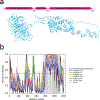
Sequence analysis of Sec31. a) Schematic diagram and flexibly fitted model from crystal structures of Sec31 domains (ΔC half-edge model derived from wt map) (Noble et al., 2012). Marked residues 387–442 contain the Sec13 binding β-sheet and the two coil regions connecting it to the N-terminal β-propeller domain and the C-terminal ACE1 domain. The latter coil region is also known as the hinge which enables the flexing of the ACE1 domain (Fig 5e). Residues 752–1273 (not shown) are known to constitute a disordered region for which there is no crystal structure or electron-microscopy map which is followed by a small α-helical domain. b) Intrinsic disorder propensity analysis of human Sec31A sequence by a set of commonly used disorder predictors, PONDR® VLXT, PONDR® VL3, PONDR® VSL2, IUPred_long and IUPred_short. Mean disorder propensity represent averaged disorder scores per residue from six individual predictors (indicated in the figure legend). All the scores consistently indicate a high disorder propensity (above 0.5) for the C-terminal region except for the small α-helical domain. Positions of potential disorder-based binding sites found by ANCHOR are shown by gray shaded areas.
Figure 2.
Figure 2.
Biophysical characterization of Sec13/31ΔC compared to wt Sec13/31. a) Distributions of hydrodynamic radii obtained from dynamic light scattering on Sec13/31ΔC heterotetramers in buffers with 10mM, 50mM, 250mM, 450mM, and 700mM concentrations of KOAc. wt Sec13/31 heterotetramers form cages with a diameter of 60nm at 700mM concentration of KOAc. As the graph indicates, the peak of the hydrodynamic radii distribution shifts to a bigger radius as the salt concentration reaches 700mM. The peak of the curve corresponding to 700mM actually happens at 33.7nm which is smaller than the expected value of 60nm. This is in part due to the high ionic concentration medium which reduces the measured hydrodynamic radius indirectly. b) Exemplar negative-staining image of COPII cages made of Sec13/31ΔC and formed in 700mM KOAC buffer. c) Assessing the thermodynamic stability of edges and cages made of wt Sec13/31 and Sec13/31ΔC. Edges and cages are represented by solid lines and dashed lines, respectively, and the wt and the construct are represented by black and red curves, respectively. The cages have an additional minimum in the curve compared to the edges at a temperature of 65 °C for the wt and 62 °C for the ΔC construct. This difference between the melting behavior of cages and edges is attributed to the structural difference between the two structures, namely, the β-propeller contacts that are essential for cage assembly. Although the difference between the wt and the construct for this minimum is small, the difference between the two for the first minimum is around 10 °C. This minimum is attributed to the edge domains that are not involved in the β-propeller contacts at the center of the vertices such as the flexible ACE1 domain. d) Distribution of particle sizes for wt Sec13/31 and Sec13/31ΔC in cage-assembly buffer. According to literature, the sedimentation coefficient of cuboctahedrons is around 60 S. Both histograms show an abundance of particles at that size, but the ΔC construct is more constrained and homogenous in terms of particle size.
Figure 3.
Figure 3.
Heterogeneous structures present in Sec13/31ΔC cages. a) 3D classification and alignment of particle images without imposing symmetry. All classes represented with different colors. The classes in yellow and purple show the most structural integrity of a Sec13/31 cage. b-d) Three different vertices from the cage class represented in yellow in a. The edges shown in e are pointed to with arrows in b and c. f-h) Symmetrically refined structure from the second and fourth classes shown in a. Panels f-h show views along the fourfold, threefold, and twofold symmetry axes, respectively. Due to symmetry, all the vertices look the same, and they represent an average of all the different conformations of vertices with a huge contour for the central density of the vertices which leaves a lot of room for different models to fit inside. i) Structure of a wt vertex for comparison. The positions of the three different domains that make up the whole vertex are marked. The density contours of Sec13 and Sec31 β-propeller domains in panels f-h are broader than that of the wt shown in i.
Figure 4.
Figure 4.
Two vertex classes from localized reconstruction and their comparison to Sec13/31ΔC and wt Sec13/31 vertices. a) Top: the top view of refined vertex class 1; bottom: comparison of density contours of the refined vertex versus an averaged vertex from the refined cage which is represented as the transparent density. The central density region of the refined vertex shows relatively better-defined contours which is an indicator of less heterogeneity. b) Same representation as in a for refined vertex class 2. c) Side view of class 2 (transparent green density), with its plus-ends lying in the plane of the page, and rigidly fitted to the wt vertex (magenta). The smaller curvature of ACE1 domain of plus ends of class 2 are easily noticeable as well as the shift of Sec13. d) A thin slice through the plus ends as shown in the small inset. The centers of Sec13 and ACE1 domain are used to measure the angles. Class 2 exhibits a less acute curvature (162°) than wt vertex (135°). e) A close look at the center of the vertex along the 2-fold symmetry axis. The center of wt Sec13 (blue arrow), the center of Sec13 of class 2 (white arrow), and the point on the 2-fold symmetry axis (the shared end of the arrows) lie in a plane perpendicular to the symmetry axis (the arrows are elevated for representation purposes). In that plane, the center of Sec13 shifts ~11 Å between class 2 and wt vertex.
Figure 5.
Figure 5.
Flexible fitting of ΔC edge models derived from wt map into ΔC maps. a) Left: superimposition of the plus end dimer (yellow) and the minus end dimer (green) of class 2, with the plane of the figure being the same as the plane which is normal to the four-fold axis of the cage, this view will be called the top view. Right: superimposition of the same dimers with a view perpendicular to the top view, this view will be called the side view. b) Left: superimposition of the plus end of class 2 and the plus end of the wt (purple), top view. Right: superimposition of the same dimers, side view. c) Left: superimposition of the minus end of class 2 and the minus end of wild type (blue), top view. Right: superimposition of the same dimers, side view. d) Left: superimposition of the plus end and the minus end of wild type, top view. Right: superimposition of the same dimers, side view. e) Schematic diagram of the domain shifts that illustrate a new hinge motion between the two β-propeller domains and a new mode of flexibility for the ACE1 domain. The plus-end of class 2 and wt are represented in light grey and dark grey, respectively, with a top view on the left-hand side and a side view on the right-hand side. f) Left: class 2 density and the flexibly fitted ΔC edge model. Right: side view along the arrow’s direction at a lower isosurface threshold. g) Left: class 1 density and the flexibly fitted ΔC edge model. Right: side view along the arrowhead’s direction at a lower isosurface threshold.
Figure 6.
Figure 6.
Reconstitution of possible heterotetramer conformations using the central dimers of flexibly fitted vertex structures. All dimers in this panel are color-coded according to their origin (refer to the legend). These conformational variations lend more support to the hypothesis that the C-terminal region of Sec31 has a structure regulation role beside the previously introduced biochemical roles.

Similar articles

Cited by

References

    1. Barlowe C, 1994. COPII: A membrane coat formed by Sec proteins that drive vesicle budding from the endoplasmic reticulum. Cell 77, 895–907. doi:10.1016/0092-8674(94)90138-4 - DOI - PubMed
    1. Bi X, Corpina RA, Goldberg J, 2002. Structure of the Sec23/24–Sar1 pre-budding complex of the COPII vesicle coat. Nature 419, 271–277. doi:10.1038/nature01040 - DOI - PubMed
    1. Bi X, Mancias JD, Goldberg J, 2007. Insights into COPII Coat Nucleation from the Structure of Sec23•Sar1 Complexed with the Active Fragment of Sec31. Developmental Cell 13, 635–645. doi:10.1016/j.devcel.2007.10.006 - DOI - PMC - PubMed
    1. Boivin S, Kozak S, Meijers R, 2013. Optimization of protein purification and characterization using Thermofluor screens. Protein Expression and Purification 91, 192–206. doi:10.1016/j.pep.2013.08.002 - DOI - PubMed
    1. Brohawn SG, Leksa NC, Spear ED, Rajashankar KR, Schwartz TU, 2008. Structural evidence for common ancestry of the nuclear pore complex and vesicle coats. Science 322, 1369–1373. doi:10.1126/science.1165886 - DOI - PMC - PubMed

Publication types

MeSH terms

LinkOut - more resources