S4-S5 linker movement during activation and inactivation in voltage-gated K+ channels
- PMID: 29959207
- PMCID: PMC6055142
- DOI: 10.1073/pnas.1719105115
S4-S5 linker movement during activation and inactivation in voltage-gated K+ channels
Abstract
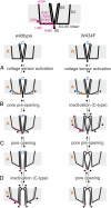
The S4-S5 linker physically links voltage sensor and pore domain in voltage-gated ion channels and is essential for electromechanical coupling between both domains. Little dynamic information is available on the movement of the cytosolic S4-S5 linker due to lack of a direct electrical or optical readout. To understand the movements of the gating machinery during activation and inactivation, we incorporated fluorescent unnatural amino acids at four positions along the linker of the Shaker KV channel. Using two-color voltage-clamp fluorometry, we compared S4-S5 linker movements with charge displacement, S4 movement, and pore opening. We found that the proximal S4-S5 linker moves with the S4 helix throughout the gating process, whereas the distal portion undergoes a separate motion related to late gating transitions. Both pore and S4-S5 linker undergo rearrangements during C-type inactivation. In presence of accelerated C-type inactivation, the energetic coupling between movement of the distal S4-S5 linker and pore opening disappears.
Keywords: Anap; inactivation; unnatural amino acids; voltage-clamp fluorometry; voltage-gated potassium channels.
Conflict of interest statement
The authors declare no conflict of interest.
Figures


Similar articles
-
The isolated voltage sensing domain of the Shaker potassium channel forms a voltage-gated cation channel.Elife. 2016 Oct 6;5:e18130. doi: 10.7554/eLife.18130. Elife. 2016. PMID: 27710769 Free PMC article.
-
Mode shift of the voltage sensors in Shaker K+ channels is caused by energetic coupling to the pore domain.J Gen Physiol. 2011 May;137(5):455-72. doi: 10.1085/jgp.201010573. J Gen Physiol. 2011. PMID: 21518834 Free PMC article.
-
A direct demonstration of closed-state inactivation of K+ channels at low pH.J Gen Physiol. 2007 May;129(5):437-55. doi: 10.1085/jgp.200709774. J Gen Physiol. 2007. PMID: 17470663 Free PMC article.
-
Involvement of the S4-S5 linker and the C-linker domain regions to voltage-gating in plant Shaker channels: comparison with animal HCN and Kv channels.Plant Signal Behav. 2014;9(10):e972892. doi: 10.4161/15592316.2014.972892. Plant Signal Behav. 2014. PMID: 25482770 Free PMC article. Review.
-
Voltage sensor movement in the hERG K+ channel.Novartis Found Symp. 2005;266:46-52; discussion 52-6, 95-9. doi: 10.1002/047002142x.ch5. Novartis Found Symp. 2005. PMID: 16050261 Review.
Cited by
-
A small-molecule activation mechanism that directly opens the KCNQ2 channel.Nat Chem Biol. 2024 Jul;20(7):847-856. doi: 10.1038/s41589-023-01515-y. Epub 2024 Jan 2. Nat Chem Biol. 2024. PMID: 38167918
-
Protons in Gating the Kv1.2 Channel: A Calculated Set of Protonation States in Response to Polarization/Depolarization of the Channel, with the Complete Proposed Proton Path from Voltage Sensing Domain to Gate.Membranes (Basel). 2022 Jul 20;12(7):718. doi: 10.3390/membranes12070718. Membranes (Basel). 2022. PMID: 35877921 Free PMC article.
-
Insights into the molecular mechanism for hyperpolarization-dependent activation of HCN channels.Proc Natl Acad Sci U S A. 2018 Aug 21;115(34):E8086-E8095. doi: 10.1073/pnas.1805596115. Epub 2018 Aug 3. Proc Natl Acad Sci U S A. 2018. PMID: 30076228 Free PMC article.
-
Molecular Insights Into the Gating Kinetics of the Cardiac hERG Channel, Illuminated by Structure and Molecular Dynamics.Front Pharmacol. 2021 Jun 8;12:687007. doi: 10.3389/fphar.2021.687007. eCollection 2021. Front Pharmacol. 2021. PMID: 34168566 Free PMC article. Review.
-
Mechanistic insights into robust cardiac I Ks potassium channel activation by aromatic polyunsaturated fatty acid analogues.bioRxiv [Preprint]. 2023 Jan 15:2023.01.12.523777. doi: 10.1101/2023.01.12.523777. bioRxiv. 2023. Update in: Elife. 2023 Jun 23;12:e85773. doi: 10.7554/eLife.85773 PMID: 36711783 Free PMC article. Updated. Preprint.
References
-
- Long SB, Campbell EB, Mackinnon R. Crystal structure of a mammalian voltage-dependent Shaker family K+ channel. Science. 2005;309:897–903. - PubMed
-
- Long SB, Tao X, Campbell EB, MacKinnon R. Atomic structure of a voltage-dependent K+ channel in a lipid membrane-like environment. Nature. 2007;450:376–382. - PubMed
-
- Bezanilla F. How membrane proteins sense voltage. Nat Rev Mol Cell Biol. 2008;9:323–332. - PubMed
Publication types
MeSH terms
Substances
Grants and funding
LinkOut - more resources
Full Text Sources
Other Literature Sources
Molecular Biology Databases

