Molecular Tension Probes for Imaging Forces at the Cell Surface
- PMID: 29160067
- PMCID: PMC6066286
- DOI: 10.1021/acs.accounts.7b00305
Molecular Tension Probes for Imaging Forces at the Cell Surface
Abstract
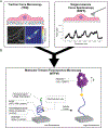
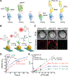
Mechanical forces are essential for a variety of biological processes ranging from transcription and translation to cell adhesion, migration, and differentiation. Through the activation of mechanosensitive signaling pathways, cells sense and respond to physical stimuli from the surrounding environment, a process widely known as mechanotransduction. At the cell membrane, many signaling receptors, such as integrins, cadherins and T- or B-cell receptors, bind to their ligands on the surface of adjacent cells or the extracellular matrix (ECM) to mediate mechanotransduction. Upon ligation, these receptor-ligand bonds transmit piconewton (pN) mechanical forces that are generated, in part, by the cytoskeleton. Importantly, these forces expose cryptic sites within mechanosensitive proteins and modulate the binding kinetics (on/off rate) of receptor-ligand complexes to further fine-tune mechanotransduction and the corresponding cell behavior. Over the past three decades, two categories of methods have been developed to measure cell receptor forces. The first class is traction force microscopy (TFM) and micropost array detectors (mPADs). In these methods, cells are cultured on elastic polymers or microstructures that deform under mechanical forces. The second category of techniques is single molecule force spectroscopy (SMFS) including atomic force microscopy (AFM), optical or magnetic tweezers, and biomembrane force probe (BFP). In SMFS, the experimenter applies external forces to probe the mechanics of individual cells or single receptor-ligand complexes, serially, one bond at a time. Although these techniques are powerful, the limited throughput of SMFS and the nN force sensitivity of TFM have hindered further elucidation of the molecular mechanisms of mechanotransduction. In this Account, we introduce the recent advent of molecular tension fluorescence microscopy (MTFM) as an emerging tool for molecular imaging of receptor mechanics in living cells. MTFM probes are composed of an extendable linker, such as polymer, oligonucleotide, or protein, and flanked by a fluorophore and quencher. By measuring the fluorescence emission of immobilized MTFM probes, one can infer the extension of the linker and the externally applied force. Thus, MTFM combines aspects of TFM and SMFS to optically report receptor forces across the entire cell surface with pN sensitivity. Specifically, we provide an in-depth review of MTFM probe design, which includes the extendable "spring", spectroscopic ruler, surface immobilization chemistry, and ligand design strategies. We also demonstrate the strengths and weaknesses of different versions of MTFM probes by discussing case studies involving the pN forces involved in epidermal growth factor receptor, integrin, and T-cell receptor signaling pathways. Lastly, we present a brief future outlook, primarily from a chemists' perspective, on the challenges and opportunities for the design of next generation MTFM probes.
Conflict of interest statement
The authors declare no competing financial interest
Figures


Similar articles
-
Molecular Tension Probes to Quantify Cell-Generated Mechanical Forces.Mol Cells. 2022 Jan 31;45(1):26-32. doi: 10.14348/molcells.2022.2049. Mol Cells. 2022. PMID: 35114645 Free PMC article. Review.
-
All-Covalent Nuclease-Resistant and Hydrogel-Tethered DNA Hairpin Probes Map pN Cell Traction Forces.ACS Appl Mater Interfaces. 2023 Jul 19;15(28):33362-33372. doi: 10.1021/acsami.3c04826. Epub 2023 Jul 6. ACS Appl Mater Interfaces. 2023. PMID: 37409737 Free PMC article.
-
Measuring Integrin Force Loading Rates Using a Two-Step DNA Tension Sensor.J Am Chem Soc. 2024 Aug 21;146(33):23034-23043. doi: 10.1021/jacs.4c03629. Epub 2024 Aug 12. J Am Chem Soc. 2024. PMID: 39133202 Free PMC article.
-
Two-Dimensional Analysis of Cross-Junctional Molecular Interaction by Force Probes.Methods Mol Biol. 2017;1584:231-258. doi: 10.1007/978-1-4939-6881-7_15. Methods Mol Biol. 2017. PMID: 28255706
-
Investigating piconewton forces in cells by FRET-based molecular force microscopy.J Struct Biol. 2017 Jan;197(1):37-42. doi: 10.1016/j.jsb.2016.03.011. Epub 2016 Mar 12. J Struct Biol. 2017. PMID: 26980477 Review.
Cited by
-
Molecular Tension Sensors: Moving Beyond Force.Curr Opin Biomed Eng. 2019 Dec;12:83-94. doi: 10.1016/j.cobme.2019.10.003. Epub 2019 Oct 19. Curr Opin Biomed Eng. 2019. PMID: 32864525 Free PMC article.
-
Selective Suppression of Integrin-Ligand Binding by Single Molecular Tension Probes Mediates Directional Cell Migration.Adv Sci (Weinh). 2024 Apr;11(14):e2306497. doi: 10.1002/advs.202306497. Epub 2024 Feb 4. Adv Sci (Weinh). 2024. PMID: 38311584 Free PMC article.
-
Mechanoimmunology: molecular-scale forces govern immune cell functions.Mol Biol Cell. 2018 Aug 8;29(16):1919-1926. doi: 10.1091/mbc.E18-02-0120. Mol Biol Cell. 2018. PMID: 30088799 Free PMC article.
-
αβ T Cell Receptor Mechanosensing Forces out Serial Engagement.Trends Immunol. 2018 Aug;39(8):596-609. doi: 10.1016/j.it.2018.05.005. Epub 2018 Jul 4. Trends Immunol. 2018. PMID: 30060805 Free PMC article. Review.
-
The CAR T-Cell Mechanoimmunology at a Glance.Adv Sci (Weinh). 2020 Nov 3;7(24):2002628. doi: 10.1002/advs.202002628. eCollection 2020 Dec. Adv Sci (Weinh). 2020. PMID: 33344135 Free PMC article. Review.
References
-
- McBeath R; Pirone DM; Nelson CM; Bhadriraju K; Chen CS Cell shape, cytoskeletal tension, and RhoA regulate stem cell lineage commitment. Dev. Cell 2004, 6, 483–495. - PubMed
Publication types
MeSH terms
Substances
Grants and funding
LinkOut - more resources
Full Text Sources
Other Literature Sources
Research Materials
Miscellaneous

