

Quantitative Characterization of Domain Motions in Molecular Machines
- PMID: 28199113
- PMCID: PMC5479934
- DOI: 10.1021/acs.jpcb.6b10732
Quantitative Characterization of Domain Motions in Molecular Machines
Abstract
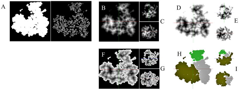
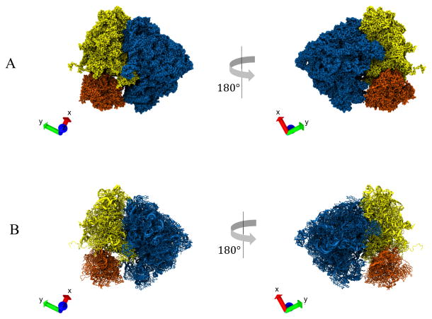
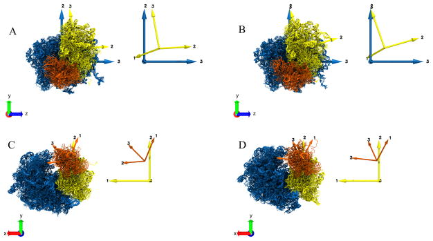
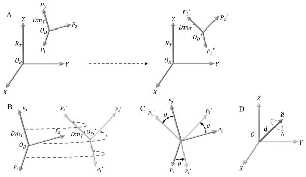
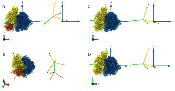
The work of molecular machines such as the ribosome is accompanied by conformational changes, often characterized by relative motions of their domains. The method we have developed seeks to quantify these motions in a general way, facilitating comparisons of results obtained by different researchers. Typically there are multiple snapshots of a structure in the form of pdb coordinates resulting from flexible fitting of low-resolution density maps, from X-ray crystallography, or from molecular dynamics simulation trajectories. Our objective is to characterize the motion of each domain as a coordinate transformation using moments of inertia tensor, a method we developed earlier. What has been missing until now are ancillary tools that make this task practical, general, and biologically informative. We have provided a comprehensive solution to this task with a set of tools implemented on the VMD platform. These tools address the need for reproducible segmentation of domains, and provide a generalized description of their motions using principal axes of inertia. Although this methodology has been specifically developed for studying ribosome motion, it is applicable to any molecular machine.
Conflict of interest statement
Notes
The authors declare no competing financial interest.
Figures
Similar articles
-
Fast fitting to low resolution density maps: elucidating large-scale motions of the ribosome.Nucleic Acids Res. 2014 Jan;42(2):e9. doi: 10.1093/nar/gkt906. Epub 2013 Sep 29. Nucleic Acids Res. 2014. PMID: 24081579 Free PMC article.
-
Trajectories of the ribosome as a Brownian nanomachine.Proc Natl Acad Sci U S A. 2014 Dec 9;111(49):17492-7. doi: 10.1073/pnas.1419276111. Epub 2014 Nov 24. Proc Natl Acad Sci U S A. 2014. PMID: 25422471 Free PMC article.
-
Ribosome dynamics: insights from atomic structure modeling into cryo-electron microscopy maps.Annu Rev Biophys Biomol Struct. 2006;35:299-317. doi: 10.1146/annurev.biophys.35.040405.101950. Annu Rev Biophys Biomol Struct. 2006. PMID: 16689638 Review.
-
Energy landscape of domain motion in glutamate dehydrogenase deduced from cryo-electron microscopy.FEBS J. 2020 Aug;287(16):3472-3493. doi: 10.1111/febs.15224. Epub 2020 Feb 5. FEBS J. 2020. PMID: 31976609
-
Structural basis for protein synthesis: snapshots of the ribosome in motion.Curr Opin Struct Biol. 2012 Dec;22(6):743-9. doi: 10.1016/j.sbi.2012.07.011. Epub 2012 Aug 4. Curr Opin Struct Biol. 2012. PMID: 22871550 Free PMC article. Review.
Cited by
-
Cryo-EM shows stages of initial codon selection on the ribosome by aa-tRNA in ternary complex with GTP and the GTPase-deficient EF-TuH84A.Nucleic Acids Res. 2018 Jun 20;46(11):5861-5874. doi: 10.1093/nar/gky346. Nucleic Acids Res. 2018. PMID: 29733411 Free PMC article.
-
The translation elongation cycle-capturing multiple states by cryo-electron microscopy.Philos Trans R Soc Lond B Biol Sci. 2017 Mar 19;372(1716):20160180. doi: 10.1098/rstb.2016.0180. Philos Trans R Soc Lond B Biol Sci. 2017. PMID: 28138066 Free PMC article. Review.
-
A Multi-model Approach to Assessing Local and Global Cryo-EM Map Quality.Structure. 2019 Feb 5;27(2):344-358.e3. doi: 10.1016/j.str.2018.10.003. Epub 2018 Nov 15. Structure. 2019. PMID: 30449687 Free PMC article.
-
Tools for the cryo-EM gold rush: going from the cryo-EM map to the atomistic model.Biosci Rep. 2017 Dec 5;37(6):BSR20170072. doi: 10.1042/BSR20170072. Print 2017 Dec 22. Biosci Rep. 2017. PMID: 28963369 Free PMC article. Review.
-
Time resolution in cryo-EM using a novel PDMS-based microfluidic chip assembly and its application to the study of HflX-mediated ribosome recycling.bioRxiv [Preprint]. 2023 Jul 29:2023.01.25.525430. doi: 10.1101/2023.01.25.525430. bioRxiv. 2023. Update in: Cell. 2024 Feb 1;187(3):782-796.e23. doi: 10.1016/j.cell.2023.12.027. PMID: 36747778 Free PMC article. Updated. Preprint.
References
-
- Humphrey W, Dalke A, Schulten K. VMD: visual molecular dynamics. Journal of molecular graphics. 1996;14(1):33–8. 27–8. - PubMed
Publication types
MeSH terms
Grants and funding
LinkOut - more resources
Full Text Sources
Other Literature Sources
