Review
. 2015 Jul;104(4):334-50.
doi: 10.1002/bip.22639.

Protein design: Past, present, and future

Affiliations
Review

Protein design: Past, present, and future

Lynne Regan et al. Biopolymers. 2015 Jul.

Abstract

Building on the pioneering work of Ho and DeGrado (J Am Chem Soc 1987, 109, 6751-6758) in the late 1980s, protein design approaches have revealed many fundamental features of protein structure and stability. We are now in the era that the early work presaged - the design of new proteins with practical applications and uses. Here we briefly survey some past milestones in protein design, in addition to highlighting recent progress and future aspirations.

Keywords: computation; nanotechnology; protein design; review.


Figures

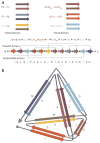
FIGURE 1
FIGURE 1
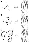
Schematic illustration of a systematic, minimal approach to the design of the four-helix bundle protein. From Regan, L.; DeGrado, W. F. Science 1988, 241, 976–978. Reprinted with permission from AAAS.
FIGURE 2
FIGURE 2
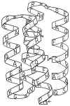
Schematic illustration showing both the sequence and proposed three-dimensional structure of the designed four-helix bundle protein, Felix. From Hecht, M. H.; Richardson, J. S.; Richardson, D. C.; Ogden, R. C. Science 1990, 249, 884–891. Reprinted with permission from AAAS.
FIGURE 3
FIGURE 3
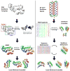
Comparison of ORBIT and RosettaDesign design strategies. Left: In ORBIT a backbone template with known coordinates is chosen. Amino acid positions are classified into three categories: core, boundary, and surface. Dead-End Elimination is implemented to reduce the combinatorial search of energetically allowed rotamers and to obtain the global minimum energy conformation (GMEC). Lastly, Monte Carlo is used to randomly change rotamers of the GMEC sequence to sample local low-energy configurations. Right: In RosettaDesign an ensemble of de novo backbones is generated using peptide fragments that match the desired backbone. This ensemble is subjected to iterative rounds of fixed backbone sequence optimization and flexible backbone energy minimization. Amino acid sequences are optimized by sampling different residues and rotamers with a Monte Carlo search protocol. Backbones are optimized by perturbing main-chain torsion angles, cycling through rotamers for side-chains with increased energies, and minimizing backbone energy at insertion sites according to the Metropolis criterion. The table of PDB fragments in the right column is reprinted with permission from Kaufmann, K. W.; Lemmon, G. H.; Deluca, S. L.; Sheehan, J. H.; Meiler, J. Biochemistry 2010, 49(14), 2987–2998. © 2010 American Chemical Society.
FIGURE 4
FIGURE 4
The CHAMP design process. A transmembrane helix-helix backbone pair with the desired geometry is selected from a database of membrane-protein structures (left). The original amino acid side-chains are discarded, and the helical backbones are extended to span the full length of a membrane. Next, the sequence from the target TM protein is “threaded” onto either one of the helices—in this example, the right helix with green side-chains (middle). Last, the sequence and side-chain configurations for the anti-TM peptide (represented by the left helix) is chosen via iteration over amino acids and rotamer re-packing (right). From Yin, H.; Slusky, J. S.; Berger, B. W.; Walters, R. S.; Vilaire, G; Litvinov, R.I.; Lear, J. D.; Caputo, G. A.; Bennett, J. S.; DeGrado, W. F. Science 2007, 315(5820), 1817–1822. Reprinted with permission from AAAS.
FIGURE 5
FIGURE 5
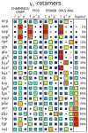
Comparing the performance of different force-fields in predicting side-chain dihedral angle distributions. Comparison of the relative populations of χ1 dihedral angles (where t =120° <χ1 <240°, g+=240° <χ1 <360°, and g−=0° <χ1 <120°) for different amino acids resulting from simulations of short peptides in solution, using different force-fields (CHARMM22/CMAP; FF03; FF99SB; OPLS-AA/L). The relative occupancy of each side-chain dihedral is indicated by the size and color of the associated square (see legend). Each row shows the predictions for that particular amino acid type given by the specified force-field. A good “consistent” prediction would be if each force-field gave the same result. Lys is quite good. By contrast, Val is particularly bad since its results differ with each force-field. Reprinted with permission from Vymětal, J.; Vondrášek, J. Journal of Chemical Theory and Computation 2013, 9, 441–451.© 2013 American Chemical Society.
FIGURE 6
FIGURE 6
Comparison of force-field performance in simulations of the 78 amino acid protein, ubiquitin. 524 different parameters were used in the assessment of the score. Each column corresponds to a given force field (as indicted) and each row corresponds to a different model for explicit solvent (as indicated). For each combination of force field and water model, χ2 quantifies the agreement between simulation and experiment based on the 524 parameters, indicated by the color of the square. A smaller value of χ2 (darker blue) indicates a greater agreement between prediction and experiment. Note the differences between the different force fields with the same water models, and between different water models with the same force field. Reprinted with permission from Beauchamp, K. A.; Lin, Y. S.; Das, R.; Pande, V. S. Journal of Chemical Theory and Computation 2012, 8, 1409–1414. © 2012 American Chemical Society.
FIGURE 7
FIGURE 7
Comparison between different probability distributions P(ψ,ϕ) for the backbone dihedral angles φ and ψ obtained from molecular dynamics simulations of an Ala dipeptide mimetic using different versions of the CHARMM and Amber force-fields, their associated optimized water models, and with and without the “ILDN-NMR” and “CMAP” dihedral angle potential corrections. Outlined are the Ramachandran hard sphere limits for 110°. (a) Amber99sb +TIP4P-Ew, (b) Amber99sb-ILDN-NMR +TIP4P-Ew, (c) CHARMM27 +TIP3SP, and (d) CHARMM27-CMAP +TIP3SP. Panels (e) and (f) correspond to the Alanine phi/psi distributions different subsets of the PDB. Note the different predictions in panels (a)–(d) compared with the experimental values in panels (e),(f). Reprinted with permission from Caballero, D.; Määttä, J.; Zhou, A. Q.; Sammalkorpi, M.; O’Hern, C. S.; Regan, L. Protein Science 2014, 23, 970–980.
FIGURE 8
FIGURE 8
Creation of a temperature-responsive hydrogel, based on a “dual network” design. (a) Illustration of the components of the dual polymer design comprising PNIPAM ends (green), helical coiled coils (dark blue), and linker regions (pale blue). (b) Schematic representation of the temperature-dependent reinforcement of shear-thinning hydrogels by the PNIPAM triblock copolymer domains. At 4°C, the coiled coils (dark blue) fold and associate, while the PNIPAM domains (green lines) do not interact. However, at 37°C the PNIPAM blocks associate (green spheres) and reinforce the hydrogel network. Reprinted with permission from Glassman, M. J.; Chan, J.; Olsen, B. D. Advanced Functional Materials. 2013, 23, 1182–1193.
FIGURE 9
FIGURE 9
A: Ribbon representation of the SpyTag-SpyCatcher complex assembly. The Lys residue (red) on the 12 kDa SpyCatcher protein spontaneously forms an isopeptide bond with the Asp (red) on the 13-reside SpyTag peptide. B: Schematic illustration of the diverse protein topologies possible by the SpyTag (red triangle)/SpyCatcher (purple crown) technology. Reprinted with permission from (A) Zakeri, B.; Fierer, J. O.; Celik, E.; Chittock, E. C.; Schwarz-Linek, U.; Moy, V. T.; Howarth, M. Proc Natl Acad Sci USA 2012, 109, E690–697, and (B) Zhang, W. B.; Sun, F.; Tirrell, D. A.; Arnold, F. H. Journal of the American Chemical Society 2013, 135, 13988–13997. © 2013 American Chemical Society.
FIGURE 10
FIGURE 10
A: Cartoon of covalent hydrogel formation using SpyTag/SpyCatcher technology. Three SpyTag sequences (red triangles) are connected by an elastin-like-protein (ELP) sequence (orange strand) to make the AAA construct. Two SpyCatcher units (purple crowns) are joined by an ELP linker to form the BB construct. Mixing these two proteins results in a covalent Spy network. B: A photograph of the formed covalent Spy network. Mixing 10% wt aqueous solutions of AAA and BB in equimolar amounts of binding sites yields the hydrogel shown. Upon addition of water, the Spy network swells by 3000% after 12 h and continues to be swollen after 48 h. FROM PNAS: Sun, F.; Zhang, W. B.; Mahdavi, A.; Arnold, F. H.; Tirrell, D. A. Proc Natl Acad Sci USA 2014, 111, 11269–11274.
FIGURE 11
FIGURE 11
A schematic illustration of the reversible formation of a TPR-peptide based hydrogel. Consensus TPR “binding” modules (dark blue) that bind to the cognate peptide are concatenated with TPR “spacer” modules (pale blue) that do not bind the peptide so that binding sites are arrayed on different faces of the cylinder. Peptide cross-linkers were constructed by chemical attachment of the cognate peptide to functionalized 4-armed star PEG molecules (black lines with red termini). Mixing the TPR arrays with PEG-peptide cross-linkers in a stoichiometric ratio of 1:2 results in hydrogel formation, which can be reversed by increasing ionic strength or decreasing pH.
FIGURE 12
FIGURE 12
Design of a tetrahedron/trigonal pyramid using coiled-coils assembly. (a) Cartoon illustrating the pyramid components—sets of heterodimeric and homodimeric parallel and anti-parallel coiled-coils. The 12 individual peptide sequences are concatenated in the indicated order, with each sequence separated by the flexible linker Ser-Gly-Pro-Gly. Grey lines indicate the interacting pairs. (b) Schematic of the desired tetrahedron structure. Arrows indicate the direction of the helices in the coiled-coil pairs. Reprinted by permission from Macmillan Publishers Ltd: [Nature Chemical Biology] Gradisar, H.; Bozic, S.; Doles, T.; Vengust, D.; Hafner-Bratkovic, I.; Mertelj, A.; Webb, B.; Sali, A.; Klavzar, S.; Jerala, R. Nat Chem Biol 2013, 9, 362–366, © 2013.
FIGURE 13
FIGURE 13
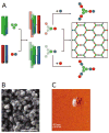
Design of “spheres” using coiled coil assemblies (SAGE). A: Design of the hubs that self-assemble to form SAGE molecules. The heterotrimeric coiled-coil (CC-Tri3, green) connects to either CC-Di-A (red) and CC-Di-B (blue) via asymmetric sulfide linkages (purple lines) to form hub A (red-green) and hub B (blue-green). Mixing of hub A and hub B yields a hexagonal array by the formation of heterodimeric coiled-coils between CC-Di-A and CC-Di-B. EM (B) and LMFM (C) images of a hydrated SAGE molecule. From Fletcher, J. M.; Harniman, R. L.; Barnes, F. R.; Boyle, A. L.; Collins, A.; Mantell, J.; Sharp, T. H.; Antognozzi, M.; Booth, P. J.; Linden, N.; Miles, M. J.; Sessions, R. B.; Verkade, P.; Woolfson, D. N. Science 2013, 340, 595–599. Reprinted with permission from AAAS.
FIGURE 14
FIGURE 14
Design of a 24-subunit protein cube. (a) The designed fusion protein with the KDPGal aldolase trimer (green) connected to the dimeric domain of FkpA protein (orange) by the helical linker (blue). The purple and cyan lines represent the two-fold and three-fold axes of symmetry, respectively. (b) A cartoon model of the 24-subunit cage design. The two-fold and three-fold axes of symmetry in the cube are shown in purple and cyan, respectively. Reprinted by permission from Macmillan Publishers Ltd: [Nature Chemistry] Lai, Y. T.; Reading, E.; Hura, G. L.; Tsai, K. L.; Laganowsky, A.; Asturias, F. J.; Tainer, J. A.; Robinson, C. V.; Yeates, T. O. Nat Chem 2014, 6, 1065–1071, © 2014.
FIGURE 15
FIGURE 15
Fluorescent proteins with a wide spectral range of excitation and emission. Reprinted with permission from Tsien, R. Y. Angewandte Chemie International Edition 2009, 48, 5612–5626.
FIGURE 16
FIGURE 16
Schematic illustration of the split GFP system used to identify protein-protein interactions. GFP is split into N-terminal (green) and C-terminal (red) halves, which do not associate on their own. Attaching two interacting proteins (depicted here are a designed pair of coiled-coil dimers) forces the two halves to associate, producing the native fold and fluorophore. Reprinted with permission from Magliery, T. J.; Wilson, C. G.; Pan, W.; Mishler, D.; Ghosh, I.; Hamilton, A. D.; Regan, L. Journal of the American Chemical Society 2005, 127, 146–157. © 2005 American Chemical Society.
FIGURE 17
FIGURE 17
Schematic illustration of the method developed by Shokat et al. to identify kinase substrates. Analogue sensitive (As)-kinase contains a mutation in the ATP binding domain that enables it to function with both ATP (A) and a bulky ATP derivative (A*), while wild-type (WT) kinase can only functional with A. Hodgson, D. R.; Schröder, M. Chemical Society Reviews 2011, 40, 1211–1223. Reproduced with permission from The Royal Society of Chemistry.
FIGURE 18
FIGURE 18
Cartoon depiction of the LOV2-based photosensitive degron (psd). Psd consists of a fusion between the LOV2 photosensitive domain and the proteasome binding peptide cODC. In the dark state, the Jα helix on the LOV2 domain is folded and associates with cODC, preventing it from interacting with the proteasome. Absorption of blue light triggers unfolding of Jα, releasing the cODC peptide to bind the proteasome and induce degradation of the psd module, along with any protein fused to it. Reprinted from Chemistry & Biology, Vol 20, Renicke, C.; Schuster, D.; Usherenko, S.; Essen, L. O.; Taxis, C., “A LOV2 Domain-Based Optogenetic Tool to Control Protein Degradation and Cellular function,” 619–626, © 2013, with permission from Elsevier.

Similar articles

Cited by

References

    1. Murphy GS, Sathyamoorthy B, Der BS, Machius MC, Pulavarti SV, Szyperski T, Kuhlman B. Protein Sci. 2014;4:434–445. - PMC - PubMed
    1. Ho SP, DeGrado WF. J Am Chem Soc. 1987;109:6751–6758.
    1. Regan L, DeGrado WF. Science. 1988;241:976–978. - PubMed
    1. Hecht MH, Richardson JS, Richardson DC, Ogden RC. Science. 1990;249:884–891. - PubMed
    1. Padmanabhan S, Marqusee S, Ridgeway T, Laue TM, Baldwin RL. Nature. 1990;344:268–270. - PubMed

Publication types

LinkOut - more resources