. 2015 Feb 26:6:6337.
doi: 10.1038/ncomms7337.

Structural basis for self-assembly of a cytolytic pore lined by protein and lipid

Affiliations

Structural basis for self-assembly of a cytolytic pore lined by protein and lipid

Koji Tanaka et al. Nat Commun. .

Abstract

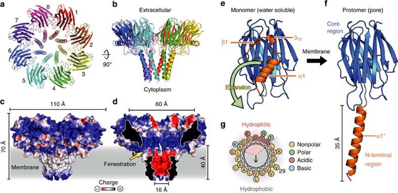
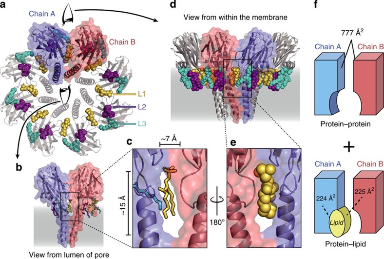
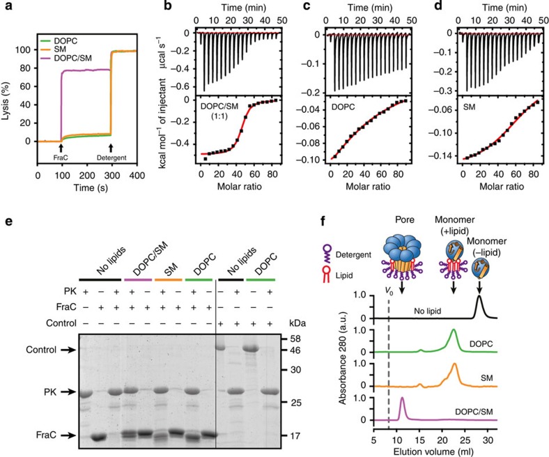
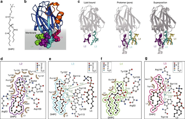
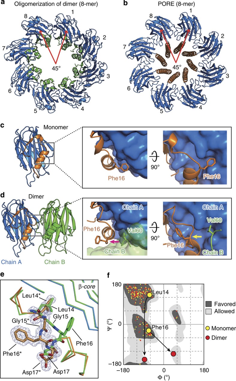
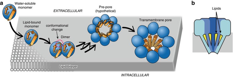
Pore-forming toxins (PFT) are water-soluble proteins that possess the remarkable ability to self-assemble on the membrane of target cells, where they form pores causing cell damage. Here, we elucidate the mechanism of action of the haemolytic protein fragaceatoxin C (FraC), a α-barrel PFT, by determining the crystal structures of FraC at four different stages of the lytic mechanism, namely the water-soluble state, the monomeric lipid-bound form, an assembly intermediate and the fully assembled transmembrane pore. The structure of the transmembrane pore exhibits a unique architecture composed of both protein and lipids, with some of the lipids lining the pore wall, acting as assembly cofactors. The pore also exhibits lateral fenestrations that expose the hydrophobic core of the membrane to the aqueous environment. The incorporation of lipids from the target membrane within the structure of the pore provides a membrane-specific trigger for the activation of a haemolytic toxin.


Figures

Figure 1
Figure 1. Structure of the transmembrane pore of FraC.
(a) Top view. The pore is composed of eight identical protein chains (protomers). Lipid molecules are not shown. (b) Side-view showing the funnel-like shape of the pore. (c) Electrostatic potential of the outer surface of the pore. The colour gradient from red to blue represents negative (−3 kT) to positive electrostatic potentials (+3 kT). The plasma membrane region is represented in gray. (d) Electrostatic potential in the lumen of the pore. Colour scheme is same as above. Cross-section reveals distinctive fenestrations (windows) exposing the hydrophobic core of the membrane to the aqueous phase. (e) Representative structure of water-soluble (monomeric) FraC. The N-terminal region and the β-core are depicted in orange and blue, respectively. (f) Structure of a protomer of FraC inserted in the membrane. A large conformational change involving the first 29 residues of the N-terminal region (orange), but not the β-core, is clearly observed. (g) Helical wheel representation of the N-terminal amphipathic α-helix inserted in the membrane.
Figure 2
Figure 2. Lipids are integral part of the structure of the pore.
(a) Top view of the pore depicting the bridging lipid (L1, yellow) and the annular lipids (L2, purple; L3, cyan). Lipids are depicted as space-filling models. (b) Lateral view (from the lumen of the pore) of two protein chains and the relative position of the associated lipids. The protein is shown as transparent surfaces and cartoons, and the lipids are depicted as solid sticks. (c) Close-up view of the non-annular lipid L1. (d) View of the pore from the lipid phase. (e) Close-up view of non-annular lipid L1 as seen from the lipid phase. (f) Schematic model of the composite interaction surface of the pore. The values correspond to the protein–protein contact interface and the lipid–protein contact interface as calculated by the PISA server.
Figure 3
Figure 3. Functional analysis.
(a) Lytic activity of FraC in vesicles made of different lipid compositions. Addition of protein and detergent are indicated by arrows. Complete lysis (100% signal) was obtained by adding detergent TX-100 at a final concentration of 0.1% v-v. (bd) Characterization of binding of FraC to liposomes made of different lipid compositions by ITC. The upper panel corresponds to the titration. The bottom panel corresponds to the binding isotherm obtained from the titration curve. The red trace corresponds to the non-linear fitting of the integrated heat to a one-site model with ORIGIN. The lipid composition is indicated in each panel (b, DOPC/SM (1:1); c, DOPC; d, SM). (e) Protection assay. FraC was treated with PK in the presence or absence of vesicles. A control experiment was performed with bovine serum albumin as a substrate, demonstrating that the activity of PK is not inhibited by liposomes. (f) Influence of the lipid composition in the assembly of FraC. Liposomes were treated with FraC, followed by solubilization with TX-100 and purified in the presence of LDAO. The black solid line corresponds to a control experiment in the absence of liposomes and detergents. The void volume (Vo) was 8 ml (vertical dashed line). FraC, detergent and lipid are represented using schematic cartoons. The orange rectangle and the blue sphere represent the N-terminal region and the β-core region of FraC, respectively.
Figure 4
Figure 4. Structure of lipid-bound FraC.
(a) Chemical formula of the lipid DHPC. (b) Overall structure of FraC with DHPC bound. The structure reveals up to four lipids bound to a single chain of FraC, although only two binding sites are conserved in all the protein chains refined (10 protein chains in three different spacegroups). The clustering of the lipids around FraC suggests the orientation of the protein with respect to the plane of the membrane. The lipids termed L2, L3, L4 and L5 are depicted as space-filling models and coloured in purple, cyan, green and magenta, respectively. (c) Depiction of the two constant lipid binding sites in the structure of FraC with bound DHPC (left panel), and in the pore (centre panel). The panel on the right shows the overlay of these two structures. The non-annular lipid L1 is absent in the DHPC-bound structure. (dg) Environment around the four lipid molecules bound to an individual chain of FraC. The lipids shown are, from left to right, L2, L3, L4 and L5. Hydrogen-bond distances are shown in green.
Figure 5
Figure 5. Structure of an assembly intermediate (dimer).
(a) Top view of a hypothetical ‘pre-pore’ built from the assembly of successive dimers of FraC. To obtain this model, chain B of a fixed dimer and chain A of a mobile dimer were superimposed, after which chain A of the incoming chain was removed. This process was repeated until a complete rotation of 360 ° is obtained. Following this process yields a rotational 8-mer. We note that this octamer is not sealed at the ends. (b) Top view of the pore of FraC in the same orientation as above. (c) Crystal structure of water-soluble FraC (no lipids bound), and close-up view of the region where Phe16 interacts with the β-core region. (d) Crystal structure of dimeric FraC. Molecules of POC are not shown. The close-up view reveals conformational changes at Phe16 and adjacent residues with respect to the monomer. Dimerization is characterized by the displacement of the side chain of Phe16 by the residue Val60 of a second protein chain (green). (e) Close-up view of the conformational changes of residues 14–17 on dimerization. The mesh corresponds to the Sigma-A weighted electron density map (2Fo—Fc) contoured at σ=1.0. The chain corresponding to the monomer-like conformation is depicted in green. The main chain of the protein in the dimer-like conformation is shown in orange (N-terminal region) and blue (β-core). Residues labelled with an asterisk correspond to residues of the dimer-like conformation. (f) Ramachandran plot of water-soluble and dimeric FraC. The figure was prepared with RAMPAGE.
Figure 6
Figure 6. Model for pore formation by FraC in biological membranes.
(a) Stepwise mechanism. Water-soluble monomeric FraC binds to multiple lipids through the POC moiety of their headgroups. On binding, protein–protein interactions on the plane of the membrane facilitate dimerization and partial unfolding at the N-terminal region (red circle). In the presence of lipid rafts, coalescence of multiple chains of FraC leads to further unfolding, triggering the insertion of the N-terminal region inside the target membrane and the formation of the active transmembrane pore. The N-terminal region and the β-core region of FraC are schematically represented by orange rectangles and blue spheres, respectively. (b) Model of the hybrid protein/lipid pore of FraC. The arrows indicate the structural lipids (yellow) lining the wall of the pore and acting as assembly cofactors.

Similar articles

Cited by

References

    1. Anderluh G. & Lakey J. H. Disparate proteins use similar architectures to damage membranes. Trends Biochem. Sci. 33, 482–490 (2008). - PubMed
    1. Rosado C. J. et al.. A common fold mediates vertebrate defense and bacterial attack. Science 317, 1548–1551 (2007). - PubMed
    1. Dunstone M. A. & Tweten R. K. Packing a punch: the mechanism of pore formation by cholesterol dependent cytolysins and membrane attack complex/perforin-like proteins. Curr. Opin. Struct. Biol. 22, 342–349 (2012). - PMC - PubMed
    1. Iacovache I., van der Goot F. G. & Pernot L. Pore formation: an ancient yet complex form of attack. Biochim. Biophys. Acta 1778, 1611–1623 (2008). - PubMed
    1. Geny B. & Popoff M. R. Bacterial protein toxins and lipids: pore formation or toxin entry into cells. Biol. Cell 98, 667–678 (2006). - PubMed

Publication types