

doi: 10.1085/jgp.201210840.
Perspectives on: conformational coupling in ion channels: thermodynamics of electromechanical coupling in voltage-gated ion channels
Affiliations
- PMID: 23183697
- PMCID: PMC3514737
- DOI: 10.1085/jgp.201210840
Item in Clipboard
Perspectives on: conformational coupling in ion channels: thermodynamics of electromechanical coupling in voltage-gated ion channels
J Gen Physiol.
2012 Dec.
No abstract available
Figures
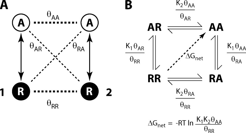
Definition of coupling. (A) Two particles, 1 and 2, each can exist in two states, R and A. Each of them have an intrinsic preference for one of the two states, which is determined by its intrinsic free-energy difference between the two states (represented by the solid arrows). There are four state-dependent interactions between them: the horizontal broken lines represent the “like state” interactions, θAA and θRR, which are the interactions when both particles are in the A or R states, respectively; the diagonal broken lines represent the “unlike state” interactions, θAR and θRA, which are the interactions when the particles are in dissimilar states. (B) The system in A is represented in a reaction scheme showing the transitions between the different states. Alongside each transition, its equilibrium constant is shown. K1 and K2 are the intrinsic activation constants of the two particles. The presence of the state-dependent interactions modifies each of the equilibrium constants, but the net free-energy difference (ΔGnet) between the doubly resting (ground) state, RR, and the doubly activated (final) state, AA, is determined by the intrinsic equilibrium constants and the like state interactions.

χ-value analysis for a voltage-dependent system comprising two particles. (A) The particle diagram for a system comprising a voltage sensor (which can exist in two states, R and A) and a pore (which exists in two states, C and O). K1 and K2 represent the intrinsic equilibrium constants of the voltage sensor and the pore in the absence of any other interactions. There are four state-dependent interaction terms between the two particles (θRC, θAC, θRO, and θAO; as in Fig. 1 A). The energetic parameters of this system can be normalized through the relations shown. The voltage dependencies of KV and KP can be expressed as: (i = V, P), where is the voltage-independent part of the equilibrium constant and zi is its voltage dependence; F, R, and T represent the Faraday constant, the universal gas constant, and the temperature, respectively. Because the four coupling constants are voltage independent, KV has the same voltage dependence as K1, and KP has the same voltage dependence as K2. The coupling parameter in the normalized version, θ, is the ratio of the like state interactions (θRCθAO) and the unlike state interactions (θACθRO). (B) Using arbitrary values of the energetic parameters, the ln(P0/1 − P0) vs. voltage plot for the pore was simulated for the allosteric model in A (closed symbols). The broken red lines are the extrapolations of the linear regimes (obtained at high and low voltages). The slope of the red lines is governed by zP. The difference of the intercepts created by the linear extrapolations on the V = 0 axis is the χdiff for pore, which is linearly proportional to the difference in the like state interaction energies (−RTln(θAOθRC)) and the unlike state interaction energies (−RTln(θACθRO)). (C) The state diagram for an allosteric model comprising two particles, using the normalized parameters: there are four possible states of the system, depending on the conformations of each of the two particles. When KP becomes very low, the allosteric model reduces to a linear sequential scheme representing an obligatorily coupled system. In terms of the un-normalized parameters, this could occur when K2 << 1, θRO << 1, and/or θRC >> 1. The ln(P0/1 − P0) vs. V plot for the pore, for the obligatorily coupled model, shown in B (open symbols), keeps on decreasing steeply at hyperpolarizing voltages.
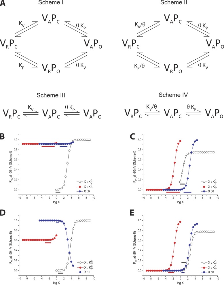
Coupling schemes to explain the opposite shifts in the activation of the voltage sensors and the pore. (A) Scheme I shows a canonical allosteric scheme showing voltage sensor activation (intrinsic equilibrium constant: ) and the pore opening (intrinsic equilibrium constant: ) being energetically connected via an interaction in the doubly activated state (where the voltage sensor is activated and the pore is open), represented by θ. Scheme II is a noncanonical counterpart of Scheme I, where the two structural units are interacting in both the doubly activated and the doubly resting state (i.e., the states where both the conformation are in “like” conformations). Schemes III and IV are obligatory analogues of Schemes I and II, respectively, where the conformational state with a resting voltage sensor and an open pore (VRPO) is eliminated. (B and C) The variation of occupancy of the activated state of the voltage sensor ( at −50 mV) and the open state of the pore ( at −20 mV) due to change in the different model parameters in Scheme I. The values for the simulations are taken from Muroi et al. (2010). Changing all the model parameters one at a time affects the two probability estimates similarly, which suggests that an opposite effect on the voltage sensor and the pore cannot be simply explained by Scheme I. The colored bars alongside the correspondingly colored curves depict the range of parameter values for which is practically constant but changes significantly. Such an effect would manifest in increased separation between the two curves. (D and E) The similar curves (as in B and C) obtained for Scheme II show that only when θ is changed do and change in an opposite way. For all other parameters, the two probability terms change in the same direction. The same observation will hold true for the obligatory schemes (III and IV); i.e., Scheme III will not yield a situation when the two probability measures are affected in opposite ways due to alteration of a single thermodynamic parameter, whereas in Scheme IV, the opposite shifts can be accomplished by altering θ.
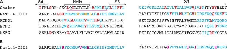
Important sites in the S4-S5 linker and S6 end region, which are putatively crucial for electromechanical coupling. (A) The S4-S5 linker and the S6 tail regions of five different voltage-gated ion channels are aligned. The demarcation of the helical regions is based on the structure of the KV1.2/2.1 chimera. In blue are the regions of the protein that have been analyzed through scanning mutagenesis, and the residues marked in red are the ones which have been proposed to be involved in coupling voltage sensor and gate motions (Shaker: Ledwell and Aldrich, 1999; Soler-Llavina et al., 2006; Batulan et al., 2010, Haddad and Blunck, 2011; NaV1.4-Domain III: Muroi et al., 2010; KCNQ1: Labro et al., 2008, ; hERG: Sanguinetti and Xu, 1999; Tristani-Firouzi et al., 2002, Van Slyke et al., 2010; HCN2: Chen et al., 2001; Decher et al., 2004). For the Shaker channel, the regions marked by the magenta bars are the complementary regions posited to be crucial for voltage sensor pore coupling in Lu et al. (2002). In the NaV sequence, the brown residues are sites that might be involved in coupling but lack the distinct phenotypic response of opposite shifts in the FV and GV curves (unlike the positions in red). (B) An orthogonal assay of coupling performed in the NaV1.4 channel (Domain III) using the lock-in strategy (see main text) identified sites (marked in magenta) within the same regions that are for the voltage sensor pore coupling (Arcisio-Miranda et al., 2010). Many of these residues coincide with or are close to sites that perturb coupling, as shown in Muroi et al. (2010; compare with residues marked in the NaV sequence in A).
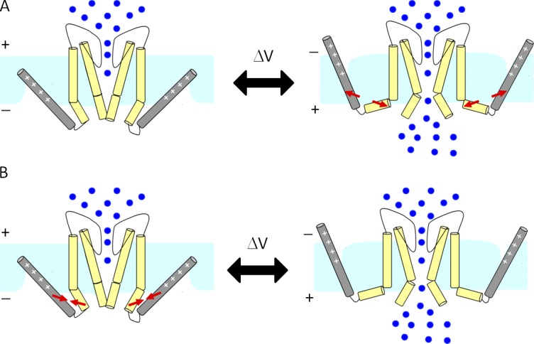
Forces governing voltage sensor pore coupling. (A) Voltage sensor pore coupling can be attractive. The voltage sensor in up conformation can pull the pore gates, which intrinsically tend to be closed, open. (B) The voltage sensor–pore interaction can be repulsive where the voltage sensor in resting state prevents the pore from opening. In this case, the pore intrinsically tends to be open, and repulsive forces between the two domains keep it closed when the voltage sensor is down conformation. The arrows show the direction of the forces. Note that these two forces are not necessarily exclusive because they occur in different conformations, and in theory they can both exist at the same time.
Similar articles
-
Structure and Sequence-based Computational Approaches to Allosteric Signal Transduction: Application to Electromechanical Coupling in Voltage-gated Ion Channels.J Mol Biol. 2021 Aug 20;433(17):167095. doi: 10.1016/j.jmb.2021.167095. Epub 2021 Jun 6. J Mol Biol. 2021. PMID: 34107281 Review.
-
Structure and function of voltage-gated ion channels.Naturwissenschaften. 1998 Sep;85(9):437-44. doi: 10.1007/s001140050527. Naturwissenschaften. 1998. PMID: 9802045 Review.
-
Perspectives on: conformational coupling in ion channels.J Gen Physiol. 2012 Dec;140(6):595-7. doi: 10.1085/jgp.201210926. J Gen Physiol. 2012. PMID: 23183695 Free PMC article. No abstract available.
-
Mapping Electromechanical Coupling Pathways in Voltage-Gated Ion Channels: Challenges and the Way Forward.J Mol Biol. 2021 Aug 20;433(17):167104. doi: 10.1016/j.jmb.2021.167104. Epub 2021 Jun 15. J Mol Biol. 2021. PMID: 34139217 Free PMC article. Review.
-
A charged view of voltage-gated ion channels.Nat Struct Biol. 2003 Jun;10(6):422-4. doi: 10.1038/nsb0603-422. Nat Struct Biol. 2003. PMID: 12768203 No abstract available.
Cited by
-
A charged residue in S4 regulates coupling among the activation gate, voltage, and Ca2+ sensors in BK channels.J Neurosci. 2014 Sep 10;34(37):12280-8. doi: 10.1523/JNEUROSCI.1174-14.2014. J Neurosci. 2014. PMID: 25209270 Free PMC article.
-
Interfacial gating triad is crucial for electromechanical transduction in voltage-activated potassium channels.J Gen Physiol. 2014 Nov;144(5):457-67. doi: 10.1085/jgp.201411185. Epub 2014 Oct 13. J Gen Physiol. 2014. PMID: 25311635 Free PMC article.
-
A self-consistent approach for determining pairwise interactions that underlie channel activation.J Gen Physiol. 2014 Nov;144(5):441-55. doi: 10.1085/jgp.201411184. Epub 2014 Oct 13. J Gen Physiol. 2014. PMID: 25311637 Free PMC article.
-
Perspectives on: conformational coupling in ion channels: conformational coupling in BK potassium channels.J Gen Physiol. 2012 Dec;140(6):625-34. doi: 10.1085/jgp.201210849. J Gen Physiol. 2012. PMID: 23183698 Free PMC article.
-
A PIP2 substitute mediates voltage sensor-pore coupling in KCNQ activation.Commun Biol. 2020 Jul 16;3(1):385. doi: 10.1038/s42003-020-1104-0. Commun Biol. 2020. PMID: 32678288 Free PMC article.
References
Publication types
MeSH terms
Substances
Grants and funding
LinkOut - more resources
Full Text Sources
