Comparative Study
. 2013 Feb;14(1):61-82.
doi: 10.1007/s10162-012-0357-9. Epub 2012 Nov 21.

Specialization for sound localization in fields A1, DZ, and PAF of cat auditory cortex

Affiliations
Comparative Study

Specialization for sound localization in fields A1, DZ, and PAF of cat auditory cortex

Chen-Chung Lee et al. J Assoc Res Otolaryngol. 2013 Feb.

Abstract

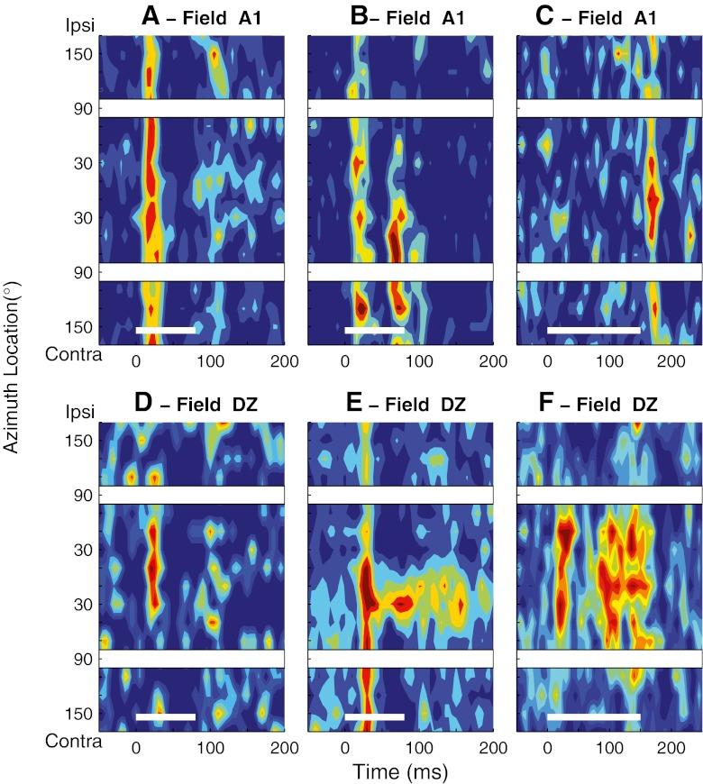
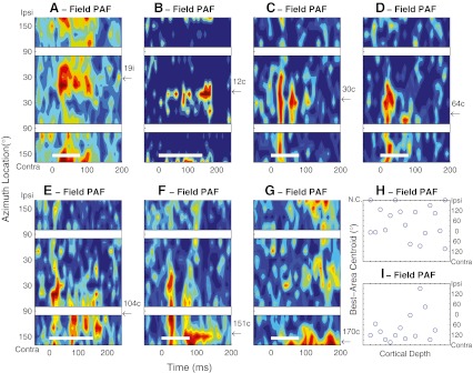
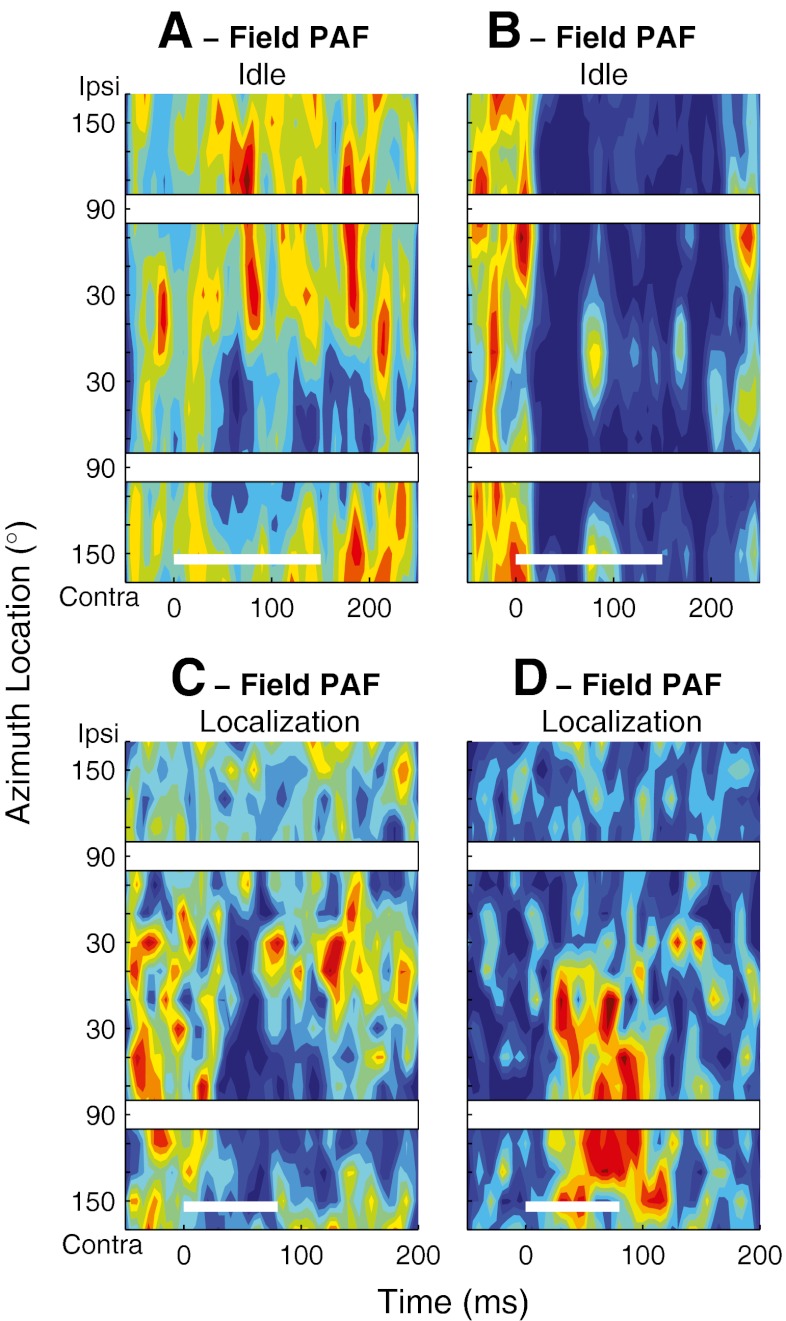
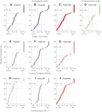
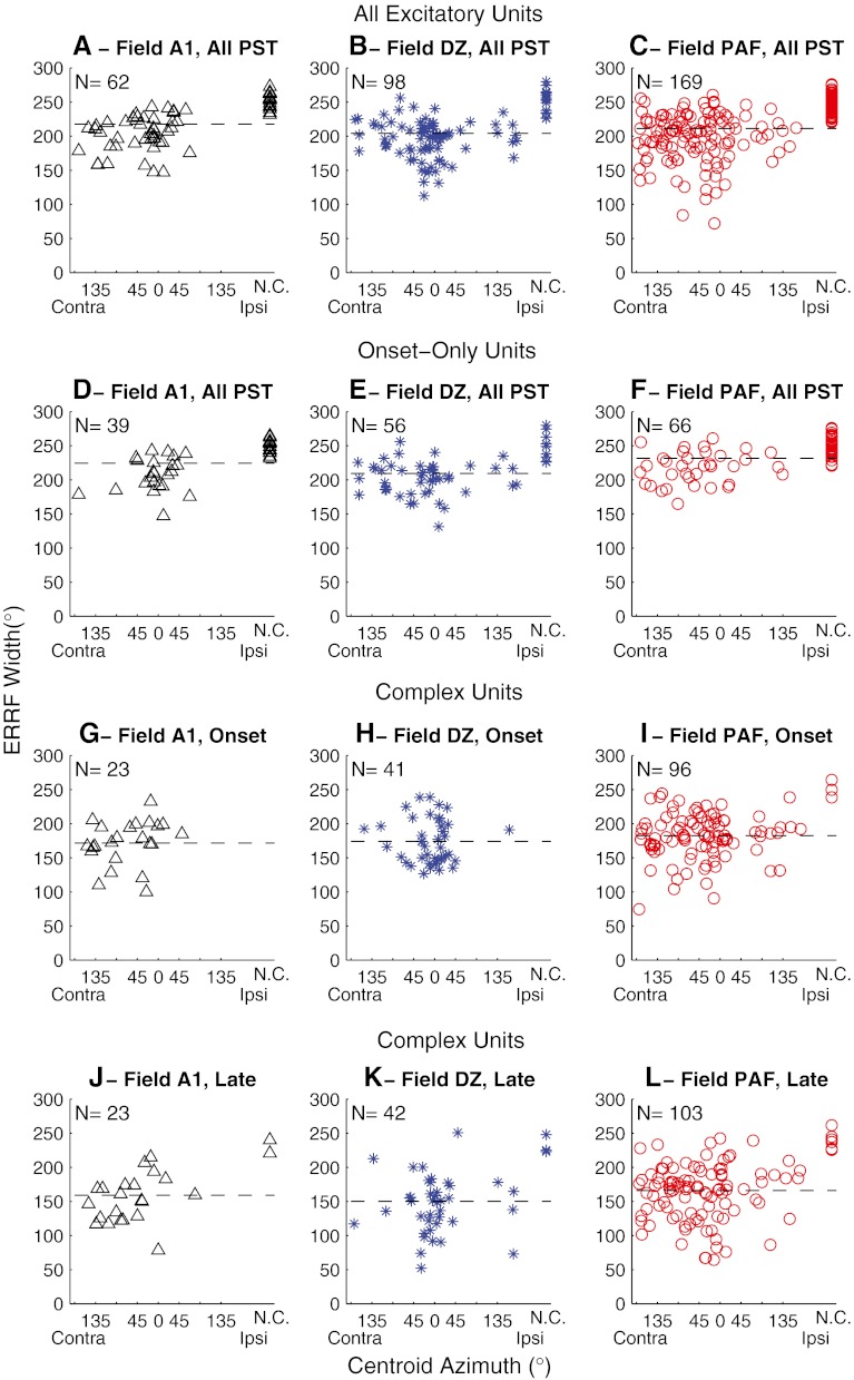
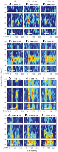
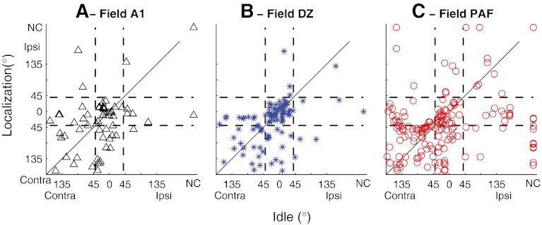
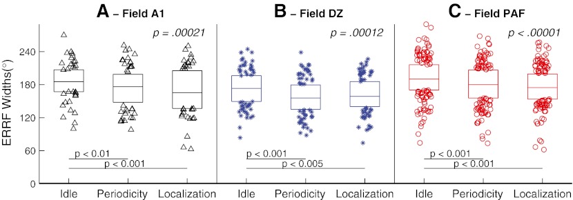
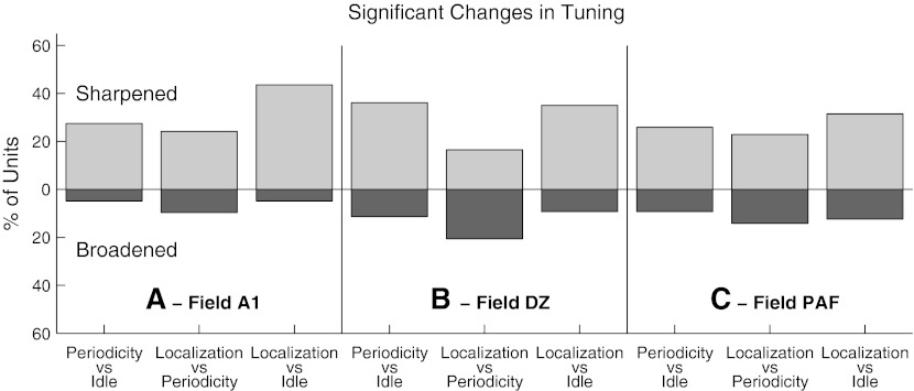
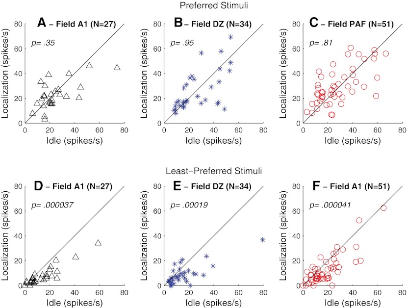
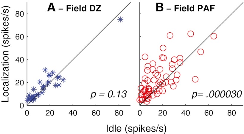
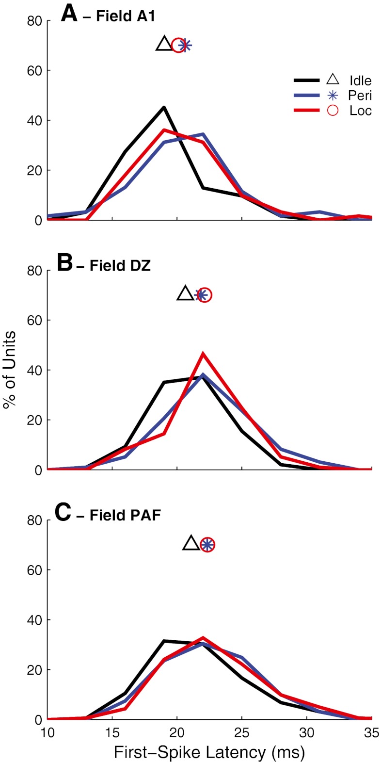
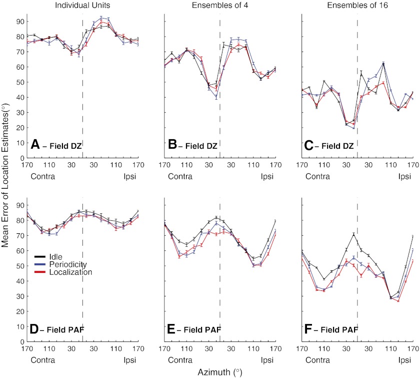
Cortical deactivation studies in cats have implicated the primary auditory cortex (A1), the dorsal zone (DZ), and the posterior auditory field (PAF) in sound localization behavior, and physiological studies in anesthetized conditions have demonstrated clear differences in spatial sensitivity among those areas. We trained cats to perform two listening tasks and then we recorded from cortical neurons in off-task and in both on-task conditions during single recording sessions. The results confirmed some of the results from anesthetized conditions and revealed unexpected differences. Neurons in each field showed a variety of firing patterns, including onset-only, complex onset and long latency, and suppression or offset. A substantial minority of units showed sharpening of spatial sensitivity, particularly that of onset responses, during task performance: 44 %, 35 %, and 31 % of units in areas A1, DZ, and PAF, respectively, showed significant spatial sharpening. Field DZ was distinguished by a larger percentage of neurons responding best to near-midline locations, whereas the spatial preferences of PAF neurons were distributed more uniformly throughout the contralateral hemifield. Those directional biases also were evident in measures of the accuracy with which neural spike patterns could signal sound locations. Field DZ provided the greatest accuracy for midline locations. The location dependence of accuracy in PAF was orthogonal to that of DZ, with the greatest accuracy for lateral locations. The results suggest a view of spatial representation in the auditory cortex in which DZ exhibits an overrepresentation of the frontal areas around the midline, whereas PAF provides a more uniform representation of contralateral space, including areas behind the head. Spatial preferences of area A1 neurons were intermediate between those of DZ and PAF, sharpening as needed for localization tasks.


Figures

Fig. 1
Fig. 1
Poststimulus time histograms (PSTHs) showing normalized mean spike rates (colors) as a function of time (horizontal axis) and head-centered stimulus azimuth (vertical axis). In each plot, the thin white lines at the bottom of the plots indicate the 80- or 150-ms stimulus duration. White gaps crossing the plots correspond to spatial bins centered at ipsilateral and contralateral 90 °, which were omitted from analysis. These PSTHs represent units studied in the Idle condition. AC Three units recorded in field A1. Maximum mean multiunit spike rates were 10.7, 11.4, and 5.7 spikes/s based on 22–43, 17–28, and 13–34 trials at each location in A, B, and C, respectively. DF Three units recorded in field DZ. Maximum mean multiunit spike rates were 7.0, 37.9, and 13.5 spikes/s based on 18–27, 21–44, and 29 to 55 trials at each location, respectively.
Fig. 2
Fig. 2
AG PSTHs of seven units recorded in field PAF in the Idle condition. Plot conventions are the same as in Figure 1. Arrows and numbers along the right axes of the panels indicate the azimuths of the best-area centroids, expressed as ipsilateral (i) or contralateral (c) relative to the recording site. Maximum mean multiunit spike rates were 31.9, 8.6, 14.7, 9.2, 16.8, 39.3, and 24.1 spikes/s based on 36–68, 16–38, 13–34, 14–28,13–34, 14–28, and 20–32 trials at each location in AG, respectively. HI Best-area centroids of 18 (H) or 14 (I) units recorded along each of two probe placements in field PAF oriented approximately perpendicular to the cortical surface. NC no centroid. NC indicates that no centroid could be computed because a unit’s spike rate did not vary sufficiently across location. The ticks on the depth axis indicate intervals of 0.1 mm along the recording probes, although the specific depths in the cortex were not verified histologically.
FIG. 3
FIG. 3
PSTHs of four units recorded in field PAF. Plot conventions are the same as in Fig. 1. AB Responses of two units in the Idle condition showing suppressive responses to sounds. Maximum mean multiunit spike rates were 36.8 and 5.0 spikes/s based on 19–31 and 18–56 trials per location in A and B, respectively. CD Responses of two units in the Localization condition recorded at sites separated by 600 μm along one probe placement. The units show complementary suppressive (C) and excitatory (D) responses with similar spatial preferences. Maximum mean multiunit spike rates were 12.3 and 13.7 spike/s based on 21–65 and 21–65 trials at each location in C and D, respectively.
Fig. 4
Fig. 4
Distributions of centroid locations. Each unit is represented by a symbol indicating the best-area centroid. Units for which no centroid (NC) could be computed are represented by symbols placed at the right edge of each plot. Units are ordered by best-area centroids. Horizontal dashed lines indicated the percentages of the populations in each condition having centroids within 45 ° of the frontal midline. The various panels show units recorded in various fields and showing various response patterns. A, B, C All units in fields A1, DZ, and PAF having any PSTH component showing excitation to sounds. D All units in field PAF showing primarily suppression or an offset response to sounds. E, F, G Units in fields A1, DZ, and PAF showing an onset response and little or no long-latency response. H, I, J Units in fields A1, DZ, and PAF having PSTHs containing onset and long-latency responses. The number of units (N) represented in each panel is indicated.
FIG. 5
FIG. 5
Breadth of spatial tuning represented by widths of equivalent rectangular receptive fields (ERRFs). The ERRF width of each unit is shown as a function of its centroid azimuth. The horizontal dashed line in each panel indicates the mean ERRF. The top row of panels (A, B, and C) represent ERRF widths computed from full recording durations (indicated “All PST”) from all units that showed an excitatory response to sounds. The second row represents units having onset-dominant responses. The third and fourth rows represent only the units that had complex PSTHs containing long-latency components. G, H, and I show ERRF widths computed from only the onset responses, whereas J, K, and L show ERRF widths computed from only the long-latency (indicated as “Late”) responses. Among the complex units, one DZ unit and seven PAF units had robust long-latency responses but inconsistent onset responses. Those units are represented in K and L but not H and I.
Fig. 6
Fig. 6
Task-dependent modulation of response pattern and spatial sensitivity in DZ and PAF. Each row of PSTHs represents data from one unit studied in three behavioral conditions during one recording session. Left, middle, and right columns of panels represents the Idle, Periodicity Detection, and Localization conditions, respectively. The color map is equalized across the three task conditions for each unit such that any particular color indicates the same spike density (spikes per time and location bin) across the three panels in each row. af Two DZ units. Maximum mean multiunit spike rates were 6.7, 9.2, 5.1, 37.9, 37.2, and 35.7 spikes/s based on 23–47, 20–47, 9–34, 21–44, 20–50, and 23–52 trials at each location. gl Two PAF units. Maximum mean multiunit spike rates were 25.6, 32.9, 27.6, 17.8, 37.2, and 18.5 spikes/s based on 29–60, 30–60, 29–63,29–48, 28–52, and 24–46 trials at each location. Plot conventions as in Fig. 1
Fig. 7
Fig. 7
Comparison of locations of best-area centroids in Idle versus Localization conditions. Centroids were computed from onset spike counts, falling between 10 and 40 ms after stimulus onset. Vertical and horizontal lines indicate loci of centroids within 45 ° of the frontal midline. Panels indicate data from field A1, DZ, or PAF, as indicated. NC indicates units for which no centroid was computed because spike rates showed less than 50 % modulation by stimulus location.
FIG. 8
FIG. 8
Distributions of onset ERRF widths in Idle, Periodicity Detection, and Localization conditions, as indicated. In the box representing each condition, horizontal lines represent 25th, 50th, and 75th percentiles, and symbols outside the boxes represent data outside the middle two quartiles. Each panel represents data from A1, DZ, or PAF, as indicated.
Fig. 9
Fig. 9
Percentage of units that showed significant sharpening (light bar above the origin) or broadening (dark bar below) of spatial tuning between pairs of behavioral conditions, as indicated. Each panel represents data from field A1, DZ, or PAF, as indicated.
FIG. 10
FIG. 10
AC Onset spike rates elicited by stimuli at preferred locations in Localization (vertical axis) versus Idle (horizontal axis) conditions. Symbols represent only the units that were excited by sounds and that showed significant task-dependent sharpening of ERRFs, as counted in Figure 9. Panels represent data from A1, DZ, or PAF, as indicated. DF Same as AC, for spike counts elicited by stimuli at least-preferred locations. p values are from a Wilcoxon paired signed-rank test.
FIG. 11
FIG. 11
Long-latency spike rates elicited by stimuli at preferred locations in Localization (vertical axis) versus Idle (horizontal axis) conditions. Symbols represent all the DZ and PAF units that had reliable long-latency responses. Wilcoxon paired signed-rank test.
FIG. 12
FIG. 12
Distributions of median values of first-spike latencies computed at the preferred locations for units in fields A1, DZ, and PAF, as indicated. Colors indicate Idle (black), Periodicity Detection (blue), and Localization (red) conditions. Symbols indicate mean values for each field.
FIG. 13
FIG. 13
Mean errors of location estimates based on spike patterns of DZ (A to C) and PAF (D to F) units, selected as described in the text. Line colors indicate behavioral conditions, as indicated. Panels indicate results from individual units (A) (D) or randomly formed ensembles of four (B) (E) or 16 (C) (F) units. Error bars represent the standard error of the mean across estimations from 24 (a) or 47 (D) individual units or from 100 randomly selected ensembles (B, C, E, F).

Similar articles

Cited by

References

    1. Barlow HB. Single units and sensation: a neuron doctrine for perceptual psychology? Perception. 1972;1:371–394. doi: 10.1068/p010371. - DOI - PubMed
    1. Carlile S, Leong P, Hyams S. The nature and distribution of errors in sound localization by human listeners. Hear Res. 1997;114:179–196. doi: 10.1016/S0378-5955(97)00161-5. - DOI - PubMed
    1. Dingle RN, Hall SE, Phillips DP. A midline azimuthal channel in human spatial hearing. Hear Res. 2010;268:67–74. doi: 10.1016/j.heares.2010.04.017. - DOI - PubMed
    1. Dingle RN, Hall SE, Phillips DP. The three-channel model of sound localization mechanisms: interaural level differences. J Acoust Soc Am. 2012;131:4023–4029. doi: 10.1121/1.3701877. - DOI - PubMed
    1. Efron B, Tibshirani R. Statistical data analysis in the computer age. Science. 1991;253:390–395. doi: 10.1126/science.253.5018.390. - DOI - PubMed

Publication types