. 2000 Nov;116(5):697-720.
doi: 10.1085/jgp.116.5.697.

Functional triads consisting of ryanodine receptors, Ca(2+) channels, and Ca(2+)-activated K(+) channels in bullfrog sympathetic neurons. Plastic modulation of action potential

Affiliations

Functional triads consisting of ryanodine receptors, Ca(2+) channels, and Ca(2+)-activated K(+) channels in bullfrog sympathetic neurons. Plastic modulation of action potential

T Akita et al. J Gen Physiol. 2000 Nov.

Abstract

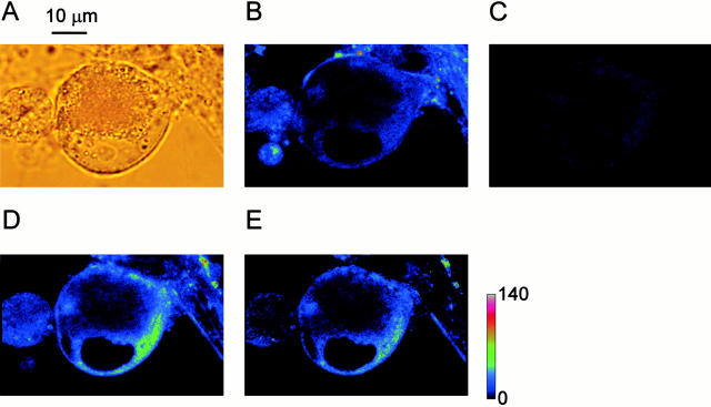
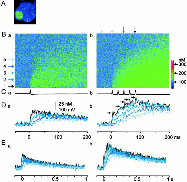
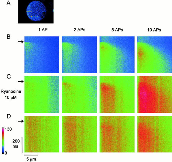
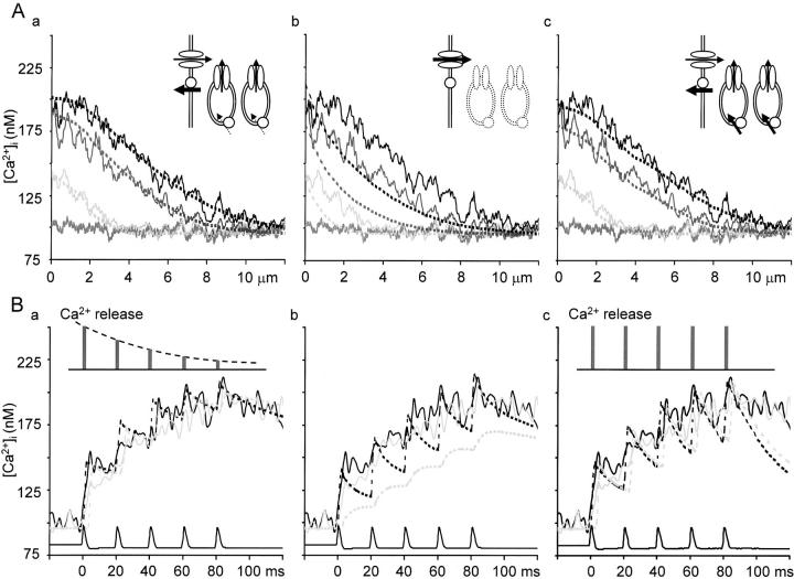
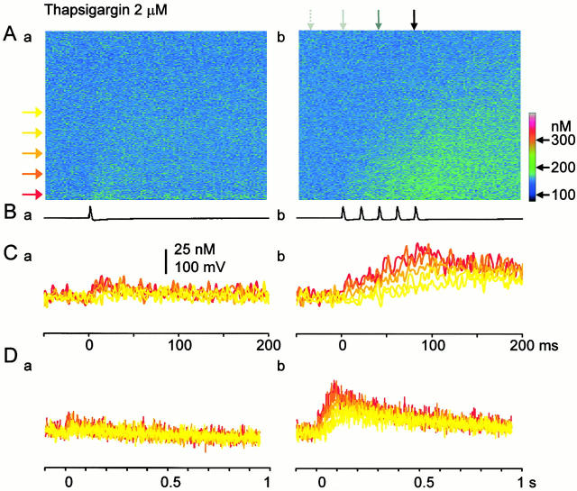
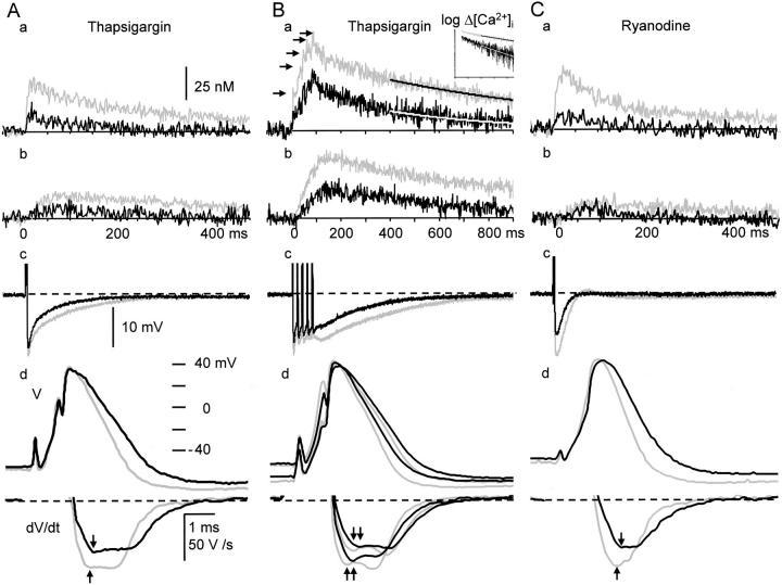
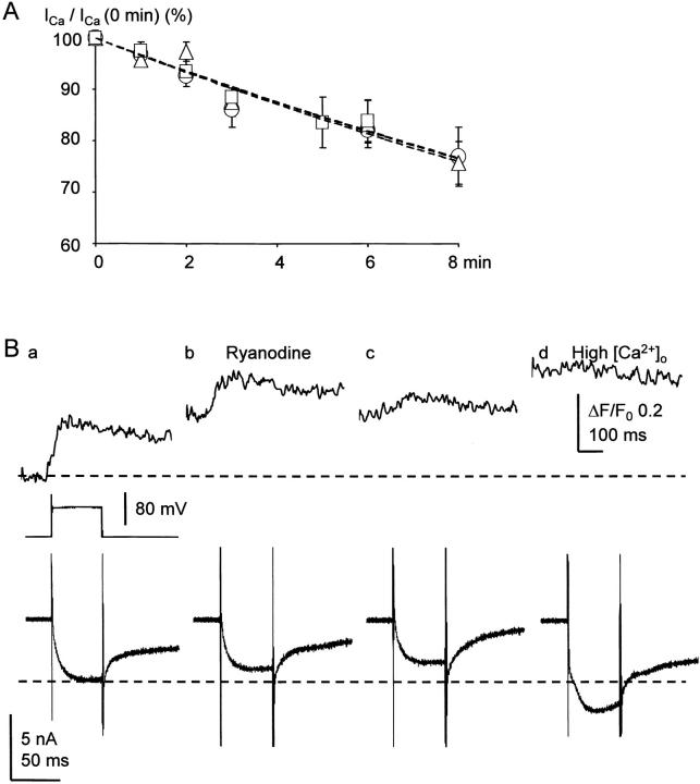
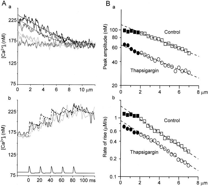
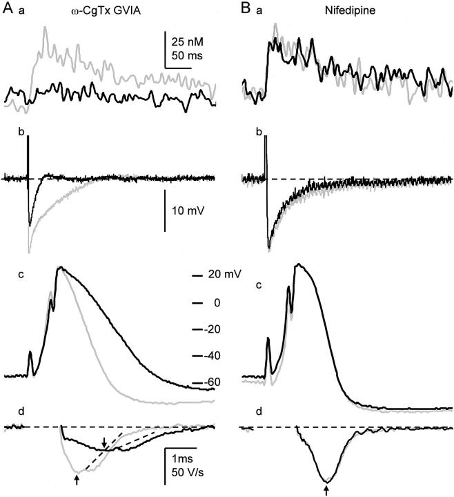
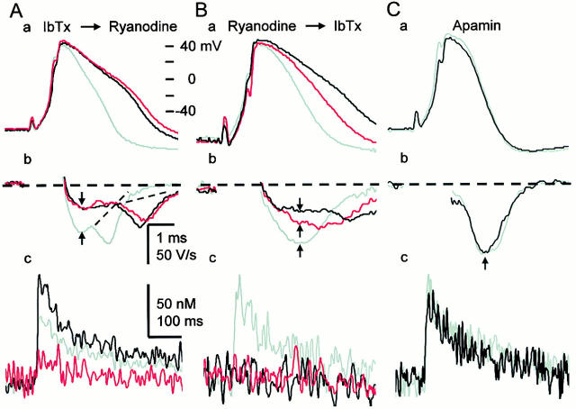
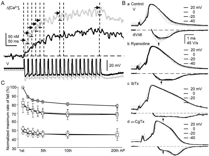
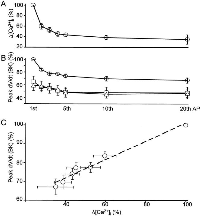
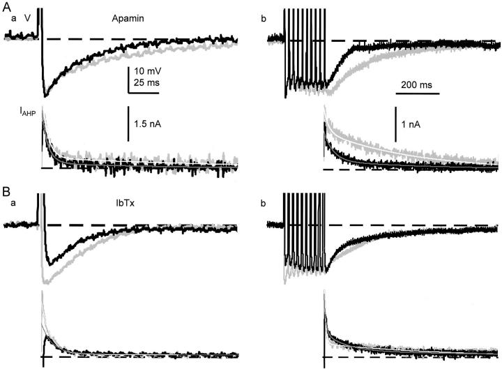
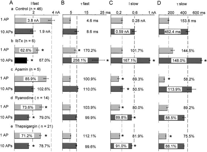
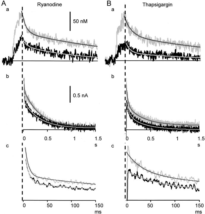
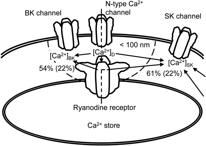
Fluorescent ryanodine revealed the distribution of ryanodine receptors in the submembrane cytoplasm (less than a few micrometers) of cultured bullfrog sympathetic ganglion cells. Rises in cytosolic Ca(2+) ([Ca(2+)](i)) elicited by single or repetitive action potentials (APs) propagated at a high speed (150 microm/s) in constant amplitude and rate of rise in the cytoplasm bearing ryanodine receptors, and then in the slower, waning manner in the deeper region. Ryanodine (10 microM), a ryanodine receptor blocker (and/or a half opener), or thapsigargin (1-2 microM), a Ca(2+)-pump blocker, or omega-conotoxin GVIA (omega-CgTx, 1 microM), a N-type Ca(2+) channel blocker, blocked the fast propagation, but did not affect the slower spread. Ca(2+) entry thus triggered the regenerative activation of Ca(2+)-induced Ca(2+) release (CICR) in the submembrane region, followed by buffered Ca(2+) diffusion in the deeper cytoplasm. Computer simulation assuming Ca(2+) release in the submembrane region reproduced the Ca(2+) dynamics. Ryanodine or thapsigargin decreased the rate of spike repolarization of an AP to 80%, but not in the presence of iberiotoxin (IbTx, 100 nM), a BK-type Ca(2+)-activated K(+) channel blocker, or omega-CgTx, both of which decreased the rate to 50%. The spike repolarization rate and the amplitude of a single AP-induced rise in [Ca(2+)](i) gradually decreased to a plateau during repetition of APs at 50 Hz, but reduced less in the presence of ryanodine or thapsigargin. The amplitude of each of the [Ca(2+)](i) rise correlated well with the reduction in the IbTx-sensitive component of spike repolarization. The apamin-sensitive SK-type Ca(2+)-activated K(+) current, underlying the afterhyperpolarization of APs, increased during repetitive APs, decayed faster than the accompanying rise in [Ca(2+)](i), and was suppressed by CICR blockers. Thus, ryanodine receptors form a functional triad with N-type Ca(2+) channels and BK channels, and a loose coupling with SK channels in bullfrog sympathetic neurons, plastically modulating AP.


Figures

Figure 1
Figure 1
Distribution of ryanodine receptors stained with fluorescent ryanodine in a cultured bullfrog sympathetic ganglion cell. (A) A bright-field image of a ganglion cell. Note the nucleus with a clear nucleolus in its center facing the lower edge of the cell. (B) The fluorescence image obtained at 10 min after the combined application of 10 μM ryanodine and 0.5 μM BODIPY FL-X ryanodine. (C) After washout of the dye and ryanodine with Ringer's solution for 30 min. (D) After reapplication of 0.5 μM BODIPY FL-X ryanodine alone for 8 min. (E) The image obtained by the subtraction of the image B from the image D. Negative values were clipped to zero. A color-coding bar shows fluorescence intensity in an arbitrary unit.
Figure 3
Figure 3
Temporal profiles of the inward spread of AP-evoked Ca2+ transients. (A) The X-Y scanned image of a ganglion cell. A yellow bar indicates the line (12 μm) scanned across the cytoplasm. (B) The fluorescence ratio images of the inward spreads of Ca2+ transients evoked by 1 AP (a) and 5 APs (b). Line-scanned fluorescence images recorded with single and five APs were divided by the image without stimulation. The lower edge of each image corresponds to the plasma membrane. Each image is the average of five scanned images obtained every 20 s. Horizontal arrows spaced every 1.5 μm indicate the positions, at which the time courses of Ca2+ transients in D and E were measured. Vertical arrows above the image (b) point the times, at which the spatial profiles of the increased [Ca2+]i shown in Fig. 4 A were taken. The arrows represent the timings of before, the first, third, and fifth AP generations, respectively. A color coding bar is expressed in [Ca2+]i values. (C) Voltage traces of an AP and APs given during the line-scans shown in B. (D and E) Time courses of Ca2+ transients at the points indicated by the horizontal arrows in B. The time scale in D is identical to those of the images in B and voltage records in C. Each trace is the average of pixel values over 0.5 μm. The black arrows in Db were added to note the progressive decrease in the amplitude of the [Ca2+]i rise during the course of APs.
Figure 2
Figure 2
The inward spread of Ca2+ transients evoked by single or repetitive APs in the submembrane region of the cytoplasm. (A) The X-Y scanned fluorescence image of a ganglion cell. A yellow bar shows the scanned line of 12 μm across the cytoplasm with no nucleus. (B) Line-scanned fluorescence images of Ca2+ transients evoked by 1, 2, 5, and 10 APs at 50 Hz. The left side edge of each image corresponds to the plasma membrane of the cell. An AP or a train of APs was elicited at the time marked by arrows. (C) The line-scanned images of AP-induced Ca2+ transients recorded at 5 min after the application of ryanodine (10 μM). (D) The images taken at 10 min after the application. Note that ryanodine initially increased the basal level of [Ca2+]i and enhanced AP-evoked Ca2+ transients (C), and then diminished the transients in this cell (D). A color bar represents fluorescence intensity in an arbitrary unit. Each line-scanned image is the average of five scanned images obtained every 20 s.
Figure 4
Figure 4
The spatial and temporal profiles of a 5APs-evoked Ca2+ transient and their reconstruction by computer simulation. (A) The spatial profiles of the Ca2+ transient and their simulation. Pale gray, dark gray, and black lines show the profiles of [Ca2+]i averaged over 10-ms periods after the generation of first, third, and fifth AP indicated by the vertical arrows in Fig. 3 B, b. The abscissas show the distances from the plasma membrane. Each trace was smoothed by the spatial running average over 0.2 μm. Shaggy, gray lines show the basal [Ca2+]i. Dotted lines show the simulated spatial profiles of [Ca2+]i under different assumptions, representing the results of temporal average over the same periods as the corresponding experimental traces. The assumptions are illustrated by the drawings in insets, including voltage-gated Ca2+ channel (ellipses) and a Ca2+-pump (a circle) at the cell membrane and Ca2+ release channels (vertical ellipses) and Ca2+ pumps (circles) at the endoplasmic reticulum (ER) membrane. Arrows indicate the direction of Ca2+ flux via these channels and pumps, the width of which reflects the relative amount of the flux to each other, defined in the modeling. See materials and methods for the details of parameters. (A, a) Simulation assuming Ca2+ release of decreasing amplitude from the submembrane ER. The magnitude of Ca2+ release was assumed to decrease exponentially. Dashed arrows beside the pumps on ER indicate that there must be a small amount of Ca2+ pump flux in the actual system, although they were not explicitly included in the modeling (see results). (A, b) Simulation assuming only the diffusion process for the transport of Ca2+ in the cytoplasm. (A, c) Simulation assuming Ca2+ release of constant amplitude and Ca2+ uptake at the ER. (B) Computer simulation of the time courses of the initial phase of the Ca2+ transient. Pale gray and black lines show the time courses of Ca2+ transients identical to the traces 1 and 2 in Fig. 3 D, b. Dotted lines represent the results of simulation averaged over the three neighboring shells (0.6-μm wide) at the regions corresponding to the experimental records. Assumptions used in the simulation B (a–c) were the same as those of A (a–c), respectively. Voltage traces of APs triggering the Ca2+ transient are shown at the bottom. The relative magnitudes of Ca2+ release assumed are shown in B (a and c).
Figure 5
Figure 5
Effects of thapsigargin on AP-evoked Ca2+ transients. (A–D) The inward spreads and time courses of Ca2+ transients induced by a single AP (a) and five APs (b) in the presence of thapsigargin (2 μM). Explanations are the same as those in Fig. 3B–E except that the data were taken in the presence of thapsigargin. Note that the basal [Ca2+]i increased by thapsigargin corresponds to cold colors for the clearer demonstration of Ca2+ transients. However, the difference in the [Ca2+]i level from the control is shown in the scaling of the color cord.
Figure 7
Figure 7
Effects of thapsigargin and ryanodine on the spikes and AHP of APs and the accompanying Ca2+ transient. (A) Effects of thapsigargin on single APs and Ca2+ transients. (a) and (b); single AP-induced Ca2+ transients measured at 0–1 μm (a) and 5–6 μm (b) from the plasma membrane. They consist of averaged pixel values over the regions obtained from five ratio images taken at 20-s intervals. Each Ca2+ transient is shown by the net change in [Ca2+]i. Thapsigargin increased the basal [Ca2+]i by 23 nM in this cell. (c) The AHPs of APs in the same time scale as the Ca2+ transients. (d) Spikes and their rates of fall of the APs. Gray and black traces indicate the records before and 10 min after the application of thapsigargin (1 μM), respectively. The derivatives of the spikes during current stimulation were omitted. Vertical arrows indicate the points at which the rates of spike repolarization were compared. (B) Effects of thapsigargin on repetitive APs and Ca2+ transients. Explanations are essentially the same as those in A except for the following points. The spikes of the first and fifth APs and their derivatives are shown in d. The spikes of shorter duration and their greater derivatives in gray and black traces correspond to those of the first APs. Smooth lines superimposed on the Ca2+ traces in a show the results of single exponential fittings over a period beginning at 400 ms after the first of stimuli, at which the spatial gradient of [Ca2+]i disappeared. The inset in a shows the same decay time course of the [Ca2+]i in semi-logarithmic scale. Black horizontal arrows in a note progressive decreases in the amplitude of [Ca2+]i rises induced by individual APs. (C) Effects of ryanodine (10 μM) on the spike and AHP of a single AP and the accompanying Ca2+ transient. Ryanodine increased the basal [Ca2+]i by 85 nM from the control level in this cell. Explanations are the same as those in A.
Figure 8
Figure 8
No effects of thapsigargin and ryanodine on Ca2+ currents and their rundown and no restoring effect of high Ca2+ on the Ca2+ transients suppressed by CICR blockers. (A) The time courses of Ca2+ current rundown in the absence and presence of thapsigargin or ryanodine. A depolarizing voltage pulse from −75 to 0 mV (10–50 ms of the pulse duration) evoked Ca2+ currents. Open circles with a vertical bar indicate the mean ± SEM of the peak amplitudes of Ca2+ currents in the absence of a blocker (n = 24), whereas triangles and squares with a vertical bar are those in the presence of thapsigargin (1 μM; n = 19) and ryanodine (10 μM; n = 13), respectively. Each data point for CICR blockers was normalized to the amplitude before the application of the blockers. Dashed lines are the results of single exponential fitting with time constants of 29.2 min for the control, 30.0 and 30.2 min for those in the presence of thapsigargin and ryanodine, respectively. (B) No restoring effect of high extracellular Ca2+ on the Ca2+ transients suppressed by CICR blockers. Upper and lower traces represent Ca2+ transients (in fluorescence ratio change (ΔF/F0); to show the less possibility of the dye saturation) and Ca2+ currents induced by voltage pulses of 50 ms from −75 to 0 mV (shown in the middle trace) at 15 (a), 25 (b), 30 (c), and 35 min (d) after the opening of a membrane patch. Ca2+ transients were measured from the region of 5-μm width beneath the cell membrane. Ryanodine (10 μM) was applied immediately after the record (a). The extracellular Ca2+ concentration ([Ca2+]o) was raised to 10 mM after the end of the record (c).
Figure 6
Figure 6
Effects of thapsigargin on the spatial and temporal characteristics of a five AP-induced Ca2+ transient and their simulation. (A) The spatial (a) and temporal (b) profiles of the 5APs-evoked Ca2+ transient in the presence of thapsigargin and their simulation. Decreasing Ca2+ release and no Ca2+ uptake at Ca2+ stores was assumed in the simulations as in Fig. 4, Aa and Ba. The values assumed for all the parameters were the same as those in Fig. 4 (A and B, a) except for the amplitude of Ca2+ release (which was the half of the initial value of the control; 0.9 nA) and the increased basal [Ca2+]i (166 nM). (A, a) Continuous lines show the profiles of [Ca2+]i in the presence of thapsigargin (2 μM, 10 min) after the generation of first (pale gray), third (dark gray), and fifth AP (black) indicated by the vertical arrows in Fig. 5 A, b. The shaggy, gray line shows the basal [Ca2+]i. Dotted lines represent the simulated spatial profiles of [Ca2+]i. (A, b) The temporal profiles of [Ca2+]i identical to traces 1 and 2 in Fig. 5 C, b (solid black and gray) and their simulation (dotted black and gray). (B) The spatial decay in the peak amplitude and the rate of rise of five APs-induced Ca2+ transients toward the deeper cytoplasm. The peak amplitudes (a) and the rates of rise (b) of AP-induced Ca2+ transients in the absence (squares) and presence of thapsigargin (2 μM; circles) were plotted against the distances from the cell membrane in semi-logarithmic scale. The rate of rise in this figure was defined as the linear regression slope from the beginning of the rise to the peak. The values in the fast propagation phase are shown by closed symbols, whereas those in the slow phase are shown by open symbols. The dashed lines show the results of single exponential fitting over the points in the slow phase. Note that the points in the fast phase for both parameters deviate from the fitting in control and the deviation become small after the treatment with thapsigargin.
Figure 9
Figure 9
N-type Ca2+ channels are involved in the generation of AP-induced Ca2+ transients, spike repolarization and AHP of APs. (A) Effects of ω-CgTx (1 μM) on a single AP-induced Ca2+ transient (a), AHP (b), the spike (c), and its first derivatives (d) of the AP. AHPs are shown in the same time scale in a. Gray and black traces are the records before and 10 min after the application of ω-CgTx (1 μM), respectively. Ca2+ transients were measured from the region of 2-μm width beneath the cell membrane. The derivatives of the spikes during current stimulation were omitted. Vertical arrows indicate the points at which the rates of spike repolarization were compared. Dotted lines were drawn to illustrate no apparent changes in the second component of the rate of spike repolarization by ω-CgTx. (B) Effects of nifedipine (20 μM) on the Ca2+ transient, AHP, the spike and its first derivatives of a single AP. Explanations are the same as those in A.
Figure 10
Figure 10
CICR activates BK channels during the spike repolarization. (A) Effects of sequential applications of IbTx and ryanodine on the spike (a), its first derivatives (b), and a single AP-induced Ca2+ transient (c). Ca2+ transients were measured within the region of 2 μm below the plasma membrane and shown in net changes in [Ca2+]i. IbTx (100 nM) was first applied for 10 min, and then ryanodine (10 μM) was applied for 5 min. Gray traces indicate the records before the application of blockers, whereas black and red traces represent those after the application of IbTx and ryanodine, respectively. The derivatives of the spike during current stimulation were omitted. Vertical arrows indicate the points at which the rates of spike repolarization were measured. Dotted lines were drawn to illustrate no apparent changes in the second component of the rate of spike repolarization by the drugs. (B) Effects of sequential applications of ryanodine and IbTx on the spike (a), its first derivatives (b), and a single AP-induced Ca2+ transient (c). Ryanodine was first applied for 10 min, and then IbTx was applied for 10 min. Gray traces indicate the records before the application of the blockers, whereas red and black traces represent those after the application of ryanodine and IbTx, respectively. (C) Effects of apamin (100 nM) on the spike repolarization of AP (a and b) and the Ca2+ transient (c). Gray and black traces are the records before and 10 min after the application of apamin, respectively.
Figure 11
Figure 11
Reduction in the rate of spike repolarization and the accompanying Ca2+ transients during repetitive APs. (A) Time courses of increases in [Ca2+]i induced by 20 APs in the submembrane region and the accompanying AHPs. Upper records are the net increases in [Ca2+]i (Δ[Ca2+]i) within 2 μm from the plasma membrane, whereas lower records are the AHPs. Gray and black traces are those before and 10 min after the application of ryanodine (10 μM), respectively. Each trace of the records of [Ca2+]i changes was the average of two records and smoothed by a moving average over 6 ms. Vertical dashed lines indicate the timing of the first to fifth, tenth, and twentieth spike, corresponding to each of those of AP-evoked Δ[Ca2+]i. Horizontal short arrows and bars were added to note the decrease in the individual Δ[Ca2+]i during the repetitive APs. (B) The first, second, fifth, tenth, and twentieth APs and their first derivatives in a 50-Hz train in the absence and presence of ryanodine, IbTx and ω-CgTx. (a)Control APs; (b) APs recorded at 10 min after the application of ryanodine (10 μM). (c) APs recorded at 10 min after the application of IbTx (100 nM) following ryanodine. (d) APs in the presence of ω-CgTx (1 μM) applied for 10 min in another cell. The derivatives of the spike during the rising phase were omitted. Vertical arrows indicate the points at which the rates of spike repolarization were measured. (C) Reduction in the rate of spike repolarization during repetitive APs. The maximum rate of fall of each spike was normalized to that of the first in the absence of blockers. The mean ± SEM of pooled data obtained before (circles, n = 31) and after the application of ryanodine (10 μM, squares, n = 11), thapsigargin (1–2 μM, triangles, n = 12), ω-CgTx (1 μM, diamonds, n = 8) and IbTx (100 nM, crosses, n = 13) were plotted and bound with straight lines.
Figure 12
Figure 12
Correlation of BK channel activity to individual AP-induced rise in [Ca2+]i during repetition of APs. (A) Changes in each AP-induced increase in [Ca2+]i in the submembrane region (Δ[Ca2+]i) during a train of 20 APs at 50 Hz. Each change in Δ[Ca2+]i was normalized to that evoked by the first AP in a train in the absence of blockers. (B) Changes in IbTx-sensitive fraction of the maximum rate of spike repolarization (peak dV/dt [BK]) in the absence (open circles; n = 14) and the presence of ryanodine (squares; 10 μM, 10 min, n = 7) or thapsigargin (triangles; 1–2 μM, n = 7). The maximum rate of spike repolarization in the presence of IbTx was subtracted from each of those in the absence of IbTx. This procedure yielded the IbTx-sensitive component of spike repolarization in the presence and absence of CICR blockers. All the data were normalized to the maximum fractional decrease of the first AP in the presence of IbTx (50% of the control; see Fig. 11 C). (C) Correlation between Δ[Ca2+]i shown in A and peak dV/dt (BK) shown in B. Error bars indicate the means ± SEM. A dashed line in C expresses the slope of linear regression (0.57).
Figure 13
Figure 13
Changes in the magnitude of the contribution of BK and SK channels to the generation of AHP during repetitive stimuli. (A) Effects of apamin on the AHPs and IAHPs following single (a) and 10 (b) spikes. Gray and black traces are the records before and 10 min after the application of apamin (100 nM). (B) Effects of IbTx on the AHPs and IAHPs following single (a) and 10 (b) spikes. Gray and black traces are the records before and 10 min after the application of IbTx (100 nM). Each smooth line on the IAHP shows the result of double exponential fitting (see Fig. 14 for the amplitude and time constant of each component).
Figure 14
Figure 14
Effects of IbTx, apamin, ryanodine and thapsigargin on two components of IAHP. The time course of IAHP was fitted by the equation, IAHP = Ifast× exp(−t/τfast) + Islow × exp(−t/τslow) [nA]. (A and B) The amplitude and time constants of fast IAHP. (C and D) The amplitude and time constants of slow IAHP. Effects of the blockers are shown in percentages of control, reflected in the relative length of bars for the control. Pale and dark gray dashed lines indicate 100% level of control for each component of IAHPs after 1 AP and 10 APs, respectively. Asterisks (*) indicate that changes are significantly different from the corresponding control values (P < 0.01). Numerical values are shown only for the mean in or outside each column, whereas the SEM is shown by a horizontal bar.
Figure 15
Figure 15
Comparison of the decay time courses of AP-induced Ca2+ transients and the accompanying IAHPs and effects of ryanodine and thapsigargin on them. (A) Effects of ryanodine on the Ca2+ transient within 2 μm from the plasma membrane (a) and the corresponding IAHP (b and c) induced by 10 spikes. Gray and black traces are the records before and 10 min after the application of ryanodine (10 μM). IAHPs are shown in different time scales (b and c). The time scale of b is the same as that of the Ca2+ transient in a. Each of smooth lines on the Ca2+ transients and IAHPs shows the result of double exponential fitting to the decay phase of each trace after the end of current stimuli. (B) Effects of thapsigargin (1 μM) on the Ca2+ transient (a) and the IAHP (b and c) induced by 10 spikes. Other explanations are the same as those in A.
Figure 16
Figure 16
A scheme to illustrate spatial relationships among ryanodine receptor, N-type Ca2+ channel, BK, and SK channels. [Ca2+]D means the [Ca2+]i in the Ca2+ microdomain closed to the orifices of N-type Ca2+ channel and ryanodine receptor Ca2+ release channel. [Ca2+]BK and [Ca2+]SK are the Ca2+ concentrations involved in the activation of BK and SK channels, respectively. Arrows indicate the pathways of Ca2+ entering via N-type Ca2+ channels or ryanodine receptors. Numbers with percents indicate the fraction of the contribution of CICR to the activation of BK or SK channel involved in a single AP generated sparsely, whereas the numbers in parentheses are those during a sustained high frequency induction of APs.

Comment in

Similar articles

Cited by

References

    1. Adams P.R., Constanti A., Brown D.A., Clark R.B. Intracellular Ca2+ activates a fast voltage-sensitive K+ current in vertebrate sympathetic neurones. Nature. 1982;296:746–749. - PubMed
    1. Akita T., Kuba K. Ca2+ release from submembrane and perinuclear Ca2+ stores are involved in action potential-induced Ca2+ transients and modulation of membrane excitability in cultured bullfrog sympathetic neurons Jpn. J. Physiol. 49Suppl.1999. S120a (Abstr.).
    1. Akita T., Kuba K. Ca2+ release from the submembrane and perinuclear Ca2+ stores induced by action potentials and its modulation of the cell membrane excitability in cultured sympathetic neurons Soc. Neurosci. Abstr 25 1999. 1999b (Abstr.).
    1. Aldrich R.W., Jr., Getting P.A., Thompson S.H. Mechanism of frequency-dependent broadening of molluscan neurone soma spikes. J. Physiol. 1979;291:531–544. - PMC - PubMed
    1. Allbritton N.L., Meyer T., Stryer L. Range of messenger action of calcium ion and inositol 1,4,5-trisphosphate. Science. 1992;258:1812–1815. - PubMed

Publication types

MeSH terms