. 2000 Feb;74(3):1342-54.
doi: 10.1128/jvi.74.3.1342-1354.2000.

Molecular tectonic model of virus structural transitions: the putative cell entry states of poliovirus

Affiliations

Molecular tectonic model of virus structural transitions: the putative cell entry states of poliovirus

D M Belnap et al. J Virol. 2000 Feb.

Abstract

Upon interacting with its receptor, poliovirus undergoes conformational changes that are implicated in cell entry, including the externalization of the viral protein VP4 and the N terminus of VP1. We have determined the structures of native virions and of two putative cell entry intermediates, the 135S and 80S particles, at approximately 22-A resolution by cryo-electron microscopy. The 135S and 80S particles are both approximately 4% larger than the virion. Pseudoatomic models were constructed by adjusting the beta-barrel domains of the three capsid proteins VP1, VP2, and VP3 from their known positions in the virion to fit the 135S and 80S reconstructions. Domain movements of up to 9 A were detected, analogous to the shifting of tectonic plates. These movements create gaps between adjacent subunits. The gaps at the sites where VP1, VP2, and VP3 subunits meet are plausible candidates for the emergence of VP4 and the N terminus of VP1. The implications of these observations are discussed for models in which the externalized components form a transmembrane pore through which viral RNA enters the infected cell.


Figures
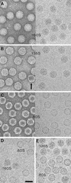
FIG. 1
FIG. 1
Electron micrographs of poliovirus 160S (A), 135S (B), and 80S (C) particles. In each case, the left-hand micrograph shows negatively stained material and the right hand micrograph shows a frozen hydrated preparation. 135S preparations usually contain a small percentage of empty 80S particles (20), e.g., the arrow in panel B. In size calibration experiments with frozen hydrated specimens, 160S was mixed with 80S (D) and 80S with 135S (E). Bar = 300 Å.
FIG. 2
FIG. 2
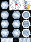
(A to C) Depiction of the 160S poliovirus particle as visualized by X-ray crystallography (31). One fivefold, one threefold, and two twofold symmetry axes are labeled. (A) Surface rendering of the outer surface, after the structure was limited to 22 Å by the procedure described (7). In panels B and C, the location of one protomer—consisting of one copy of VP1 (blue), VP2 (yellow), VP3 (red), and VP4 (green; shown only in panel C)—is marked. The five protomers that associate around a fivefold axis form a “pentamer.” In panels A and C, prominent surface features are labeled, namely, the flat top of one mesa (solid arrowhead), one arm of a mesa (shaded arrowhead), and one propeller blade tip (open arrowhead). Three VP1 loops form the top of the fivefold mesa, two portions of VP1 form a mesa arm, and portions of VP1 and VP2 form the blade tip. (D to G) Surface renderings of the 160S, 135S, and 80S cryo-EM reconstructions. Panels D and E show views of the 160S (top), 135S (middle), and 80S (bottom) particles along a twofold symmetry axis: stereo views of the outer surface are shown (D), as well as the inner surfaces (E). In panel E, RNA density was excised from the 160S and 135S structures with a spherical mask (r = 109 Å) so that the RNA-capsid contact regions appear smoothly spherical. Two twofold (lens shape), one threefold (triangle), and one fivefold (pentagon) symmetry axes in the central plane are shown. (F and G) Details of the outer surface viewed along the threefold (F) and fivefold (G) symmetry axes: 160S (left), 135S (middle), and 80S (right). Scale bar for panels A, D, E, F, and G = 100 Å.
FIG. 3
FIG. 3
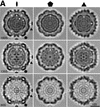
Central planar sections of the poliovirus 160S, 135S, and 80S reconstructions. Some symmetry axes are labeled. (A) Sections perpendicular to the twofold (left), fivefold (center), and threefold (right) symmetry axes. The arrows indicate the outer edge of RNA density in 160S and 135S. The arrowheads point to bubbles—regions of low density—in the middle of the capsid shell on the fivefold axes. (B) Single-level contour plots with the twofold axis normal to the page: blue, 160S; red, 135S; black, 80S. The plots are superimposed to show size relationships. The contour selected is the same level selected in Fig. 2 for the surface renderings. Bars = 100 Å.
FIG. 3
FIG. 3
Central planar sections of the poliovirus 160S, 135S, and 80S reconstructions. Some symmetry axes are labeled. (A) Sections perpendicular to the twofold (left), fivefold (center), and threefold (right) symmetry axes. The arrows indicate the outer edge of RNA density in 160S and 135S. The arrowheads point to bubbles—regions of low density—in the middle of the capsid shell on the fivefold axes. (B) Single-level contour plots with the twofold axis normal to the page: blue, 160S; red, 135S; black, 80S. The plots are superimposed to show size relationships. The contour selected is the same level selected in Fig. 2 for the surface renderings. Bars = 100 Å.
FIG. 4
FIG. 4
Polypeptide chains included in the truncated rigid-body models are shown in cyan (residues 72 to 209 and 230 to 272 of VP1), yellow (residues 72 to 265 of VP2), or red (residues 1 to 12 and 50 to 227 of VP3). Residues omitted from the model are dark blue and are labeled. The narrow end of each beta-barrel is on the top (VP1) or left (VP2 and VP3), and the wide end is opposite.
FIG. 5
FIG. 5
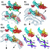
The capsid proteins VP1, VP2, and VP3 are arranged differently in each particle. (A) 160S; (B) 135S; (C) 80S. Side views of the respective models are shown in identical orientations, both alone and superimposed on a contour of the corresponding reconstructions. Five copies of residues 1 to 12 (the VP3 beta-tube) are included. In this orientation, the outer surface of the capsid faces upward. Selected fivefold and threefold axes are labeled. VP1 is cyan; VP2 is yellow; and VP3 is red. In 160S, VP4 is green. Bubbles of solvent-level density on the fivefold axis are labeled with gray arrows. (D) On the bottom, the different positions and orientations of the major capsid proteins are shown: dark blue, 160S; green, 135S; and magenta, 80S. Each capsid protein is represented in stereo by its principal axes that intersect at the center of mass. The axes were calculated from truncated alpha-carbon models, with the VP3 beta-tube (residues 1 to 12) excluded. The end of the long axes labeled VP1, VP2, or VP3 corresponds to the narrow end of the wedge-shaped beta-barrel. A truncated 160S protomer is shown in stereo in the same orientation to indicate the vantage point.
FIG. 6
FIG. 6
Close-up views of the capsids, as seen from outside, for 160S (A), 135S (B), and 80S (C). Only the core domains of the capsid proteins are shown. Fivefold and threefold axes are labeled. In each case, one protomer is shown in color: cyan, VP1; yellow, VP2; and red, VP3. Symmetry-related copies of the same proteins are dark blue. These models predict larger gaps (arrows) between subunits in the 135S and 80S capsids than in 160S.
FIG. 7
FIG. 7
A possible mechanism for transferring RNA across the cell membrane. VP1, VP2, VP3, and VP4 are colored cyan, yellow, red, and green, respectively. In the crystal structure of the virion (upper right), the beta-tube of VP3 (red) forms a plug at the fivefold axis that separates the virus interior from the outer surface. Attachment of the 160S particle (upper left) to the poliovirus receptor (three gray circles) triggers conversion to the 135S form (lower left). Upon conversion, cell attachment is mediated by externalized VP4 (green tubes) and the N termini of VP1 (blue tubes). The N termini emerge from the bottom of the canyon and extend along the sides of the fivefold mesa towards the apex. Once the N-terminal helices of VP1 have inserted into the membrane, they rearrange to form a pore (lower right). To permit the RNA (purple tube) to pass through the pore into the cytoplasm, it would be necessary for the VP3 beta-tube (red rectangle) to shift on its 40-residue tether (red tube) and for the VP1 barrels to splay farther apart.

Similar articles

Cited by

References

    1. Arita M, Horie H, Nomoto A. Interaction of poliovirus with its receptor affords a high level of infectivity to the virion in poliovirus infections mediated by the Fc receptor. J Virol. 1999;73:1066–1074. - PMC - PubMed
    1. Arita M, Koike S, Aoki J, Horie H, Nomoto A. Interaction of poliovirus with its purified receptor and conformational alteration in the virion. J Virol. 1998;72:3578–3586. - PMC - PubMed
    1. Baker T S, Cheng R H. A model-based approach for determining orientations of biological macromolecules imaged by cryo-electron microscopy. J Struct Biol. 1996;116:120–130. - PubMed
    1. Baker T S, Newcomb W W, Booy F P, Brown J C, Steven A C. Three-dimensional structures of maturable and abortive capsids of equine herpesvirus 1 from cryoelectron microscopy. J Virol. 1990;64:563–573. - PMC - PubMed
    1. Basavappa R, Syed R, Flore O, Icenogle J P, Filman D J, Hogle J M. Role and mechanism of the maturation cleavage of VP0 in poliovirus assembly: structure of the empty capsid assembly intermediate at 2.9 Å resolution. Protein Sci. 1994;3:1651–1669. - PMC - PubMed

Publication types

LinkOut - more resources