Keratocytes pull with similar forces on their dorsal and ventral surfaces
- PMID: 10601343
- PMCID: PMC2168090
- DOI: 10.1083/jcb.147.6.1313
Keratocytes pull with similar forces on their dorsal and ventral surfaces
Abstract
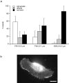
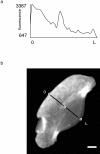
As cells move forward, they pull rearward against extracellular matrices (ECMs), exerting traction forces. However, no rearward forces have been seen in the fish keratocyte. To address this discrepancy, we have measured the propulsive forces generated by the keratocyte lamella on both the ventral and the dorsal surfaces. On the ventral surface, a micromachined device revealed that traction forces were small and rearward directed under the lamella, changed direction in front of the nucleus, and became larger under the cell body. On the dorsal surface of the lamella, an optical gradient trap measured rearward forces generated against fibronectin-coated beads. The retrograde force exerted by the cell on the bead increased in the thickened region of the lamella where myosin condensation has been observed (Svitkina, T.M., A.B. Verkhovsky, K.M. McQuade, and G. G. Borisy. 1997. J. Cell Biol. 139:397-415). Similar forces were generated on both the ventral (0.2 nN/microm(2)) and the dorsal (0.4 nN/microm(2)) surfaces of the lamella, suggesting that dorsal matrix contacts are as effectively linked to the force-generating cytoskeleton as ventral contacts. The correlation between the level of traction force and the density of myosin suggests a model for keratocyte movement in which myosin condensation in the perinuclear region generates rearward forces in the lamella and forward forces in the cell rear.
Figures


Similar articles
-
Preferential attachment of membrane glycoproteins to the cytoskeleton at the leading edge of lamella.J Cell Biol. 1991 Sep;114(5):1029-36. doi: 10.1083/jcb.114.5.1029. J Cell Biol. 1991. PMID: 1874785 Free PMC article.
-
A micromachined device provides a new bend on fibroblast traction forces.Proc Natl Acad Sci U S A. 1997 Aug 19;94(17):9114-8. doi: 10.1073/pnas.94.17.9114. Proc Natl Acad Sci U S A. 1997. PMID: 9256444 Free PMC article.
-
Separation of propulsive and adhesive traction stresses in locomoting keratocytes.J Cell Biol. 1999 May 3;145(3):589-604. doi: 10.1083/jcb.145.3.589. J Cell Biol. 1999. PMID: 10225959 Free PMC article.
-
Organization and polarity of actin filament networks in cells: implications for the mechanism of myosin-based cell motility.Biochem Soc Symp. 1999;65:173-205. Biochem Soc Symp. 1999. PMID: 10320939 Review.
-
On the mechanisms of cortical actin flow and its role in cytoskeletal organisation of fibroblasts.Symp Soc Exp Biol. 1993;47:35-56. Symp Soc Exp Biol. 1993. PMID: 8165576 Review.
Cited by
-
Slow local movements of collagen fibers by fibroblasts drive the rapid global self-organization of collagen gels.J Cell Biol. 2002 Jun 10;157(6):1083-91. doi: 10.1083/jcb.200203069. Epub 2002 Jun 10. J Cell Biol. 2002. PMID: 12058022 Free PMC article.
-
Traction forces of neutrophils migrating on compliant substrates.Biophys J. 2011 Aug 3;101(3):575-84. doi: 10.1016/j.bpj.2011.05.040. Biophys J. 2011. PMID: 21806925 Free PMC article.
-
Computational model for cell migration in three-dimensional matrices.Biophys J. 2005 Aug;89(2):1389-97. doi: 10.1529/biophysj.105.060723. Epub 2005 May 20. Biophys J. 2005. PMID: 15908579 Free PMC article.
-
Cytoskeletal coherence requires myosin-IIA contractility.J Cell Sci. 2010 Feb 1;123(Pt 3):413-23. doi: 10.1242/jcs.058297. Epub 2010 Jan 12. J Cell Sci. 2010. PMID: 20067993 Free PMC article.
-
Regulation of RhoA activity by adhesion molecules and mechanotransduction.Curr Mol Med. 2014 Feb;14(2):199-208. doi: 10.2174/1566524014666140128104541. Curr Mol Med. 2014. PMID: 24467208 Free PMC article. Review.
References
-
- Burton K., Taylor D.L. Traction forces of cytokinesis measured with optically modified elastic substrata. Nature. 1997;385:450–454. - PubMed
-
- Choquet D., Felsenfeld D.P., Sheetz M.P. Extracellular matrix rigidity causes strengthening of integrin–cytoskeleton linkages. Cell. 1997;88:39–48. - PubMed
-
- de Beus E., Jacobson K. Integrin involvement in keratocyte locomotion. Cell Motil. Cytoskel. 1998;41:126–137. - PubMed
Publication types
MeSH terms
Substances
Grants and funding
LinkOut - more resources
Full Text Sources
Other Literature Sources
Research Materials

