Abstract
As cells move forward, they pull rearward against extracellular matrices (ECMs), exerting traction forces. However, no rearward forces have been seen in the fish keratocyte. To address this discrepancy, we have measured the propulsive forces generated by the keratocyte lamella on both the ventral and the dorsal surfaces. On the ventral surface, a micromachined device revealed that traction forces were small and rearward directed under the lamella, changed direction in front of the nucleus, and became larger under the cell body. On the dorsal surface of the lamella, an optical gradient trap measured rearward forces generated against fibronectin-coated beads. The retrograde force exerted by the cell on the bead increased in the thickened region of the lamella where myosin condensation has been observed (Svitkina, T.M., A.B. Verkhovsky, K.M. McQuade, and G.G. Borisy. 1997. J. Cell Biol. 139:397–415). Similar forces were generated on both the ventral (0.2 nN/μm2) and the dorsal (0.4 nN/μm2) surfaces of the lamella, suggesting that dorsal matrix contacts are as effectively linked to the force-generating cytoskeleton as ventral contacts. The correlation between the level of traction force and the density of myosin suggests a model for keratocyte movement in which myosin condensation in the perinuclear region generates rearward forces in the lamella and forward forces in the cell rear.
Keywords: migration, traction force, cytoskeleton, micromachine, laser trap
Cell migration is an essential part of a wide range of biological phenomena, such as embryogenesis, immunological responses, and wound healing. Migration depends critically on the organized generation of cellular forces on the environment (see reviews, Lauffenburger and Horwitz 1996; Mitchison and Cramer 1996; Galbraith and Sheetz 1998). The force for migration is generated as myosin acts on the cytoskeleton and pulls against integrin–extracellular matrix (ECM) linkages to create traction forces on substratum. However, the details of the force generation mechanism, such as the pattern of migration force that the cytoskeleton exerts against the ECM coated substratum, are undefined for most cells.
The mechanism of cell migration has been extensively studied in fish keratocytes. In keratocytes, the organization of the actin–myosin (Theriot and Mitchison 1991; Small et al. 1995; Svitkina et al. 1997), the movement of myosin with respect to the actin network in the lamella region (Svitkina et al. 1997), and the orientation of the largest force that acts against the ECM-coated substratum (Lee et al. 1994; Oliver et al. 1995) have been documented. However, the largest forces against the ECM in keratocytes are oriented perpendicular to the direction of migration (Lee et al. 1994; Oliver et al. 1995). No propulsive forces acting against the substratum have been found in the direction of migration (Oliver et al. 1999), and no significant traction forces have been found in the lamella region where myosin actively reorganizes and condenses the actin network (Svitkina et al. 1997).
The orientation of the propulsive traction force is essential for determining the mechanism of migration. For example, if there are no forces directed along the axis of migration in the keratocyte, then the lamella may simply passively extend. Conversely, if there are forces acting along the axis of migration, then the keratocyte lamella may be part of a cell body contraction that advances the cell by pulling rearward in the front of the cell and pulling forward in the rear of the cell. Since large restraining forces develop when the rear of a keratocyte becomes stuck on a substratum (Galbraith, C., and M. Sheetz. 1997. Mol. Biol. Cell. 8:385; Oliver et al. 1999). One might expect that the lamella could exert proportional propulsive traction forces and, thus, be part of a cell body contraction. This scenario would suggest that keratocytes migrate by a mechanism similar to that used by fibroblasts (Harris et al. 1980; Galbraith and Sheetz 1997; Dembo and Wang 1999). Therefore, to distinguish between possible mechanisms, we need to measure these potential forces in relation to the dynamics of the force generating cytoskeleton to understand the mechanism of migration in keratocytes.
We have approached the problem of determining the propulsive forces responsible for keratocyte migration by using a micromachined substrata (Galbraith and Sheetz 1997) to measure the actual traction forces generated by the ventral surface during migration. The micromachined substratum measures the force that the cell exerts against a small distinct area of the substratum. In contrast to deformable substrata that measure forces by examining the displacement of fiduciary markers (Lee et al. 1994; Oliver et al. 1995), the micromachined substratum is not subject to cross-talk between forces emanating from distinct regions of the cell. The deformable substrata provide an excellent measure of the predominant traction pattern, but they have been unable to determine if traction forces exist under the front lamella region, possibly because lateral compression of the substratum by the traction forces perpendicular to migration has produced outward movement of the substratum in front of the cell (Lee et al. 1994). Thus, the micromachined technology allows the measured traction to be distinguished from forces generated by adhesive contacts with the ECM in neighboring regions of the cell.
Dorsal, as well as ventral, traction forces are expected from in vivo cell migration; examples include, neural crest cell migration during embryogenesis and neutrophil extravascularization during immune responses, situations where cells need to exert migration forces on both of their surfaces. However, it is currently unclear whether comparable forces can be generated against ECM contacts on both the ventral and the dorsal surface. Furthermore, migration forces have been experimentally measured on the ventral surface, but analysis of cytoskeletally mediated integrin movement has typically been made on the dorsal surface (Schmidt et al. 1993; Felsenfeld et al. 1996), which is more experimentally accessible. Dorsal surface measurements (Wang et al. 1993; Choquet et al. 1997; Lin et al. 1997) have played a central role in our understanding of traction force generation, but they are based on the assumption that forces on both surfaces are comparable, and very little information from direct measurement supports this assumption. Therefore, we have also measured the traction forces generated by the dorsal surface of the keratocyte lamella using an optical gradient trap. Both techniques measure real-time forces, but each measures different levels of force, allowing us to explore different phenomena in detail. The ventral measurements can detect large forces that act over large surface areas, and the dorsal measurement can detect small forces that act over small surface areas. These approaches are complimentary, and they allow us to compare the forces generated by both surfaces and correlate them with cytoskeletal dynamics. Moreover, comparison of the ventral and dorsal traction measurements is essential to determining whether both surfaces are functionally similar and if dorsal integrins are linked to the same cytoskeleton machinery that generates ventral forces.
Materials and Methods
Cell Culture
Goldfish were anesthetized by a brief exposure to hypothermic water and killed by decapitation, followed by pithing. Scales were removed and placed in fish Ringer's (Cooper and Schliwa 1986) supplemented with 1% Fungizone. Individual scales were teased loose from clumps and placed on 22 × 22-mm coverslips that had been cleaned with Chromerge and wetted with fish media (70% fish Ringer's, 30% Phenol red-free DME supplemented with 20% FCS, 2 mM l-glutamine, 10,000 U penicillin/streptomycin, and 20 mM Hepes). A second clean coverslip was wetted and placed over the first coverslip, creating a scale sandwich. Once the keratocytes began to crawl off the scale, usually 1–2 h, the petri dish containing the coverslips was gently flooded with fish media. Cultures were kept in a humidified chamber at room temperature until use (12–24 h).
Immunofluorescence
Keratocytes were fixed in 2% paraformaldehyde in PHEM (Schliwa and van Blerkom 1981) for 10 min. Cells were permeabilized for 0.5 min in 0.5% Triton X-100 in PBS and then blocked with 1% serum, and 0.5% BSA for 20 min. Cells were then incubated for 1 h in primary antibody, followed by a 1-h incubation in secondary antibody. Finally, coverslips were mounted in Slow Fade Light (Molecular Probes, Inc.). Three washes in PBS were performed between each step. Oregon green phalloidin was obtained from Molecular Probes, Inc., secondary antibodies were obtained from Jackson ImmunoResearch Laboratories, Inc., and the antibody to the conserved sequence of the β1 integrin (Marcantonio and Hynes 1988) was the generous gift of Richard Hynes (MIT, Cambridge, MA).
Adhesion Assay
Acid washed coverslips were silanized (Regen and Horwitz 1992) to block any surface charge. Cloning cylinders were attached to the coverslips with Sylgard 184 Elastomer (Dow Corning). The center of the coverslip was then coated with either fibronectin (FN) 120 kD (GIBCO BRL) or 2 mg/ml BSA in PBS overnight at 4°C. The adhesion assay is based on the protocol described by Ruoslahti et al. 1982. In brief, the coverslips were rinsed in PBS and blocked with 2 mg/ml BSA in PBS for at least 1 h. Cells were rinsed in Ca2+/Mg2+ free HBSS and then trypsinized with 0.05% trypsin 0.53 mM EDTA 4 Na in HBSS. Cells were rinsed in a threefold excess volume of soybean trypsin inhibitor at 1 mg/ml in PBS and gently centrifuged. Cells were resuspended in stage media (70% fish Ringer's, 30% Phenol red-free DME supplemented with 1% FCS, 2 mM l-glutamine, 10,000 U penicillin/streptomycin, and 20 mM Hepes). An equal volume of cells was added to each cloning cylinder and allowed to incubate for 60 min at room temperature. The cloning cylinder was washed with PBS and then fixed for 15 min with 4% paraformaldehyde. The cells were then fixed for an additional 1 h with 0.5% filtered Toluidine blue in 4% paraformaldehyde. The coverslips were washed with copious amounts of water, the cloning cylinders removed, and mounted with 50% glycerol in PBS.
Cells in 20 nonoverlapping fields on each coverslip were scored as either adhered and spread (spread) or adhered and not spread (round). The number of spread and round cells for each of the coverslips within a given repetition of the experiment was normalized by the maximum number of cells that adhered and spread on the FN-coated substratum.
Ventral Traction Assay
A micromachined substrata was developed to measure ventral traction forces of subcellular regions (Galbraith and Sheetz 1997). In brief, this device is based upon a system of several thousand cantilever beams buried beneath its surface. On the free end of each beam is a pad that is planar with the surface of the device. The pads range in size from 4–25 μm2. A small square hole surrounds each pad, allowing the cell to displace the pad. The force that the region of the cell in contact with the pad exerts is calculated from the displacement of the pad and the stiffness of the beam. The beams used in this study are 0.18-mm long and have a stiffness of ∼76 nN/μm as determined by calibrated microneedles (Galbraith and Sheetz 1997).
Keratocytes were grown on micromachined substratum in fish media as either explant cultures that migrated off the scale or as individual cells that had been dissociated from an explant grown on glass coverslips. In neither case was the substratum coated with matrix in addition to serum or deposited by the cell; these are the same substratum conditions that were used in the laser trap experiments. We did not coat the substratum with a more defined matrix because the micromachined devices are reused several times due to cost constraints. The micromachined devices are subjected to 10× trypsin after each use, but this does not remove all of the matrix deposited by the cells. Harsher acid treatments would remove the matrix, but they would also destroy the micromachined device. In repeated use, we have found no variation in the force produced after the device had been used once; the first use of the device typically results in poor cell adhesion, and this plating is only used to build up matrix. Furthermore, unpublished data on traction forces generated by fibroblasts where the substrate coating of laminin was varied by twofold did not show any changes in traction force, suggesting that force generation is insensitive to matrix coatings in excess of saturation level.
The substratum and cells were visualized with polarized reflection microscopy. The experiment was recorded on S-VHS tape, and individual frames were captured with a Scion LG-3 frame grabber in a Macintosh Power PC 7100. A threshold between two grey levels was applied to the image, and the centroids of the pad and the surrounding hole were calculated with NIH IMAGE 1.60 (developed at the National Institutes of Health and available by anonymous FTP from zippy.nimh.nih.gov). The centroid of the hole was subtracted from the centroid of the pad.
Dorsal Traction Assay
Carboxylate beads were coated (Felsenfeld et al. 1999) with a fragment of FNIII 7–10 (bacteria expressing FNIII 7–10 were the generous gift of Harold Erickson, Duke University, Durham, NC). Beads were constrained against the surface of keratocytes by the laser trap, and the displacement of the bead within the trap, as well as the stiffness of the trap were used to calculate the force that the cell exerted against constrained beads. Cells were prepared as described above, and the experiment was performed in stage media.
An optical gradient laser trap (Sterba and Sheetz 1998) was calibrated by moving the stage in a sinusoidal pattern and measuring the displacement of the bead from the center of the optical trap due to movement of the fluid. Using Stokes' Law, the force that the moving fluid generated against the bead was calculated. The stiffness of the trap was then determined from the slope of the fluid force vs. bead displacement curve (Svoboda and Block 1994). The displacement of the bead within the trap was measured with a nanometer-tracking routine (Gelles et al. 1988) within the program Isee (Inovision, Inc.).
The force per unit area on a 1-μm diam bead was calculated by equating the amount that the bead displaced into the cell to the centroid displacement due to focus change when the bead was initially pressed to the cell surface. The contact area was then calculated as the surface area of a zone of a sphere with this height.
Results
Ventral Traction Forces
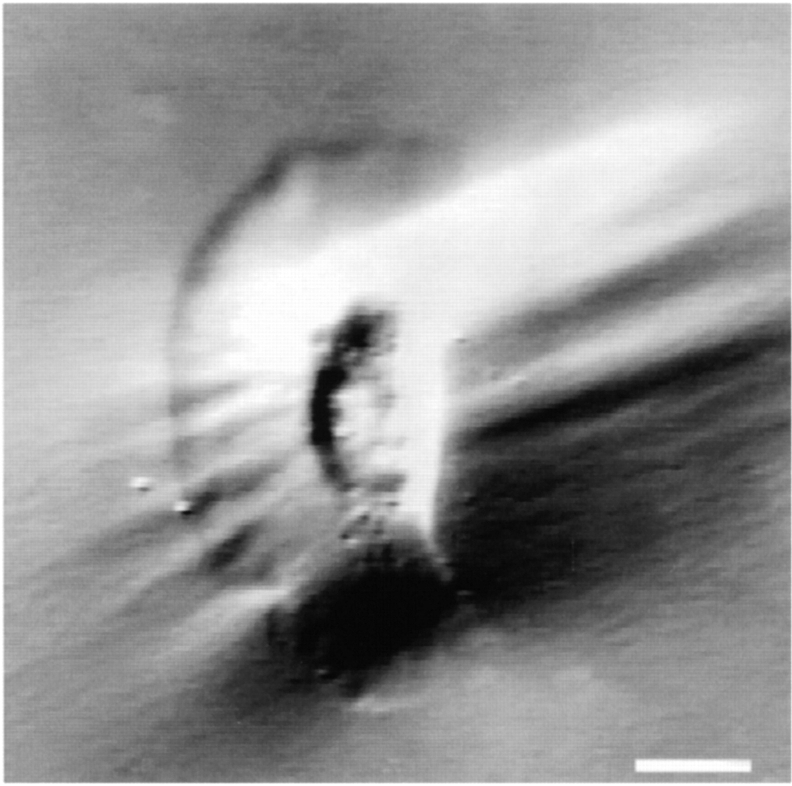
The total traction force exerted on the ventral surface of a migrating fish keratocyte is ∼45 nN (Oliver et al. 1995), an order of magnitude smaller than the migration force exerted by fibroblasts (Harris et al. 1980). The predominant ventral traction forces are perpendicular to the direction of migration. These forces are ∼20 nN in size, and they produce wrinkles in deformable substratum that are parallel to the direction of migration (Fig. 1).
Figure 1.
Keratocytes generate large traction forces orthogonal to the direction of migration. Keratocytes generate forces perpendicular to the direction of migration as indicated by wrinkles that are parallel to the direction of motion. Deformable substratum were made by cross-linking Dow Corning 710 fluid. The stiffness of the substrata was decreased by exposure to 254 nm UV light (Burton and Taylor 1997). Keratocytes generate wrinkles that are parallel to the direction of motion, indicating that the largest traction forces are perpendicular to the direction of motion. Bar, 10 μm.
To identify additional traction forces, ventral traction forces generated by subcellular regions were measured with a micromachined substratum. This device (Galbraith and Sheetz 1997) has several advantages over other techniques for measuring ventral traction forces. The device can determine the force generated by only the region of the cell contacting the measurement unit, and the measurement unit is elastic, so there is no relaxation time of the substratum to limit temporal resolution. However, since the device can only measure displacements in one direction, orthogonal to the long axis of the measurement unit, the predominant axis of force generation was derived from either deformable substrata or laser tweezer measurements.
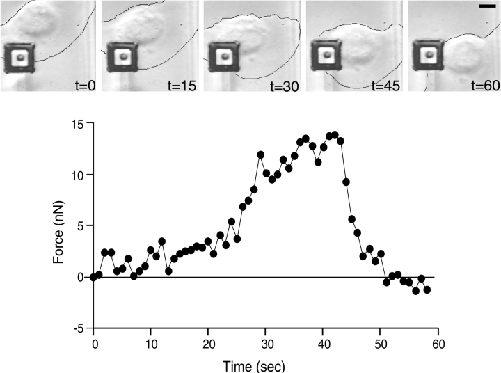
We measured the predominant traction force generated on either side of the nucleus (Fig. 2) to compare the magnitude of the force determined by our device with the force determined by other substrata. As the force vs. time trace in Fig. 2 illustrates, the maximum force that is generated by the pincer region on either side of the nucleus is ∼13 nN. Measurements made of the same region with other substratum report values as high as 11 nN (Oliver et al. 1999). Thus, both substrata measure forces of very similar magnitude in the pincer region of the cell.
Figure 2.
Traction forces on either side of the keratocyte nucleus measured with the micromachined substratum. Traction forces measured on either side of the nucleus are large and orthogonal to the direction of motion, ∼12 nN. Bar, 5 μm.
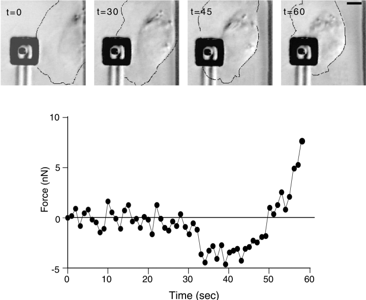
With the micromachined substratum, we were able to measure traction forces in the front region of the lamella. An example of a typical experiment is shown in Fig. 3. Initially, the lamella generated a small force directed opposite to the direction of motion; this is consistent with the forward movement of lamella fragments (Euteneuer and Schliwa 1984). This force was not detectable by our measurement device until the majority of the lamella was over the pad (Fig. 3, time [t] = 30), and then the force was only two- to threefold greater than our measurement noise. The force increased in magnitude from the front of the cell toward the perinuclear region. As the perinuclear region of the cell crossed the pad (Fig. 3t = 45) the force changed direction, and it was now oriented in the direction of motion. The maximal rearward forces were ∼4.5 nN, or 0.2 nN/μm2. This was similar to the traction forces generated by fibroblast lamella (Galbraith and Sheetz 1997), and was ∼75% less than the smallest force measured with deformable substrata (Lee et al. 1994). Thus, keratocytes, like fibroblasts, pull rearward under their lamella, change traction force direction near the nucleus (Galbraith and Sheetz 1997; Dembo and Wang 1999), and pull forward under the nucleus (data not shown).
Figure 3.
Lamella of keratocytes generate a small rearward traction force against the micromachined substratum. Bar, 5 μm. Once the lamella of a keratocyte is over the measurement pad (t = 30 s), it generates a traction force of ∼5 nN (t = 45 s) in the direction opposite that of migration, indicated as a negative force. The direction of the force changes and the magnitude increases as the thickened region of the lamella crosses the pad (t = 50 s).
Keratocytes Bind Fibronectin
Since most previous work on cytoskeletally mediated movement of integrin and ECM has been performed on the dorsal surface, we asked whether the keratocyte generates similar forces against the ECM on both the dorsal and the ventral surfaces. To measure the traction forces generated along the dorsal surface of the fish keratocyte, we probed the surface of the cell with ligand-coated beads that were held by an optical gradient trap. The generation of cellular traction forces against ECM substratum depends critically on the ligand activation of specific cell surface integrins (Choquet et al. 1997). Therefore, to characterize keratocyte forces, it was necessary to identify the binding specificity of receptors mediating substratum recognition. Specifically, we investigated whether keratocytes had an integrin that would couple FN to the cytoskeleton. FN was a likely candidate, since it had been shown that keratocyte motility is inhibited by a peptide that inhibits both FN- and vitronectin- (VN) binding to integrins (de Beus and Jacobson 1998).
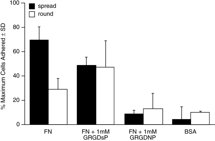
To examine the ability of keratocytes to bind FN, we performed adhesion assays. Keratocyte explant cultures were trypsinized and plated on surfaces coated with either the 120-kD fragment of FN or BSA. The percentages of cells that bound and spread on the FN-coated substrata were significantly greater than those that bound and spread on BSA-coated substrata (Fig. 4). The binding to FN was significantly inhibited by the addition of 1 mM GRGdSP, a peptide suggested to specifically inhibit cell binding to FN. Moreover, the addition of 1 mM GRGDNP, a peptide that more strongly inhibits cell binding to FN, but has some cross-inhibition with VN (Pierschbacher and Ruoslahti 1987), decreased the percentage of cells bound on FN to the same level as the BSA control (Fig. 4). Although 1 mM GRGdSP has been shown to produce half-maximal inhibition of adhesion by CHO cells to FN (Pierschbacher and Ruoslahti 1987), it was less effective in our assay, possibly due to species differences or differences in the receptor that binds FN in keratocytes. These results indicate that integrin-dependent binding and spreading does occur.
Figure 4.
Keratocytes bind to FN-coated surfaces. Individual keratocytes were plated on coverslips coated with either FN 120 kD (5 μg/ml) or BSA (2 mg/ml). The percentage of cells that bound and spread on FN-coated substrata were significantly greater than the fraction that bound to BSA-coated substrata. The binding to FN was significantly inhibited by the addition of 1 mM GRGdSP; moreover, the addition of 1 mM GRGDNP decreased the percentage of cells bound on FN to the same level as control.
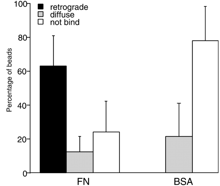
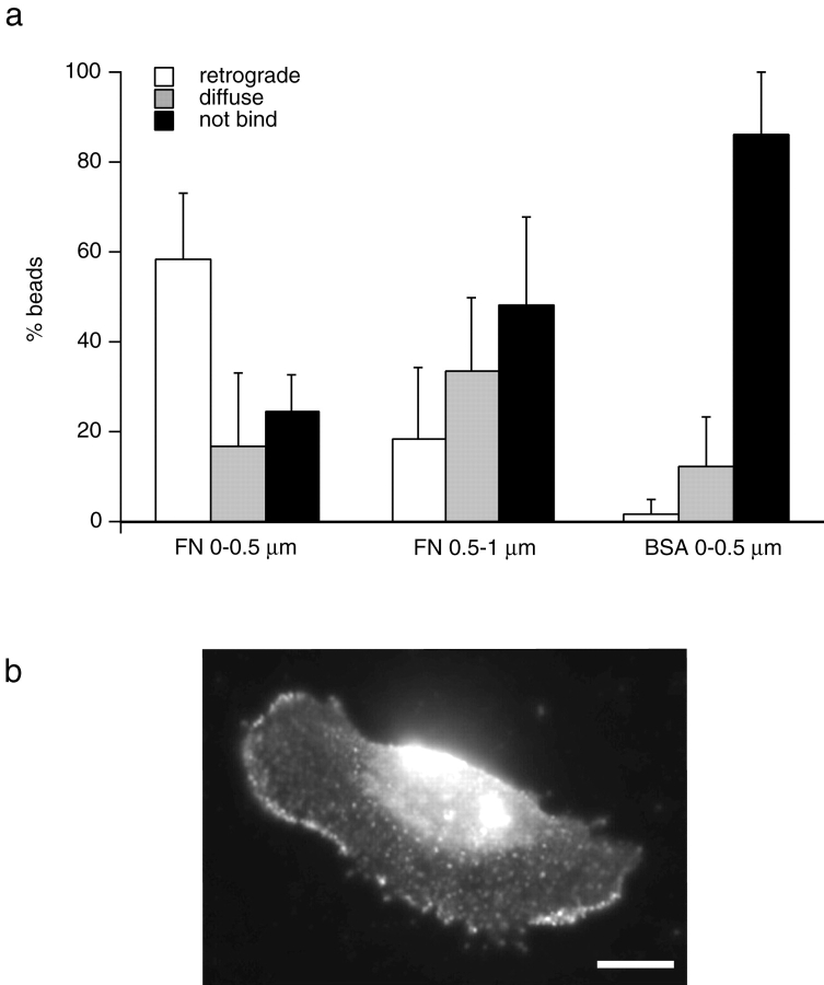
To examine ligand binding to the dorsal surface, polystyrene beads coated with either a small fragment of FN (FNIII 7–10) or with BSA were held against the cell surface by the laser trap for three seconds and then released (Fig. 5). Most of the FN-coated beads, ∼63%, bound and started to move rearward along the cell surface. In contrast, 78% of the BSA-coated beads did not bind to the cell surface, and almost none of the bound BSA-coated beads exhibited retrograde movement. Binding of FN-coated beads was not uniform across the surface, showing preferential attachment at the leading edge of the cell. The binding and retrograde movement of FN-coated beads decreased to ∼30% when the beads were placed 0.5–1.0 μm behind the leading edge of the cell (Fig. 6 a), consistent with earlier observations on fibroblasts (Nishizaka et al. 1999).
Figure 5.
Keratocytes bind and transport FN-coated beads rearward. The majority of the FN-coated beads were transported rearward by the cell once they were released from the trap. In contrast, the majority of control BSA-coated beads did not bind to the surface of the cell. FN-coated beads, n = 133; BSA-coated beads, n = 87.
Figure 6.
Keratocytes bind FN-coated beads preferentially at the leading edge. Ligand-coated beads were presented to different regions of the keratocyte lamella. a, Approximately 70% of FN-coated beads bound and moved rearward when presented at the leading edge of the cell. The percentage of bound beads decreased to ∼30% when the beads were presented 0.5–1.0 μm behind the leading edge. FN-coated beads placed on the leading edge, n = 43; FN-coated beads placed behind the leading edge, n = 43; BSA-coated beads, n = 40. b, Immunofluorescent labeling of a fish keratocyte stained with an antibody against the cytoplasmic region of the β1 integrin. Note the preferential localization of integrin along the leading edge of the lamella. Bar, 10 μm.
To determine whether preferential binding reflects integrin distribution, keratocytes were fixed and labeled with an antibody to β1 integrin, a component of the α5β1 heterodimer, a common FN receptor. The antibody is directed against the conserved cytoplasmic domain of β1 (Marcantonio and Hynes 1988). The staining was localized to the leading edge of the cell (Fig. 6 b), with an approximately twofold increase in fluorescence intensity in this region.
Measurement of Dorsal Traction Forces
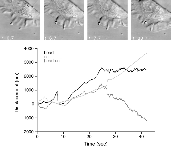
To quantify dorsal traction forces, a 1-μm diam FN-coated bead was placed on the cell surface and constrained within an optical gradient laser trap. An example of a typical experiment is shown in Fig. 7. As the cell pulled on the bead that was constrained by the laser trap, the bead displaced from the center of the trap (Fig. 7t = 7.7 s), but it did not escape from the trap. From the displacement of the bead within the trap and the stiffness of the trap, we were able to calculate that the cell exerted a force on the bead of 158 pN, or 0.4 ± 0.3 nN/μm2 (n = 7, ± SD). Eventually (Fig. 7t > 12 s), the cell exerted enough force on the bead to pull the bead from the trap. Once the bead escaped the trap, it traveled rearward with approximately the same velocity as the forward traveling cell, until it reached the nuclear region when the bead stopped moving. Moreover, this velocity is equivalent to the rate of retrograde flow of the actin cytoskeleton (data not shown).
Figure 7.
Displacement of FN-coated beads within the laser trap determines the force exerted by the dorsal surface of keratocytes. A 50-mW laser trap was used to place and hold a 1 μm bead coated with FNIII 7–10 on the lamella of a keratocyte. The cell displaces the bead with a force of 158 pN (t = 7.7 s) before it exerts enough force to escape the trap. Once the bead escapes the trap, it travels rearward at approximately the same velocity as the cell travels forward.
We were unable to measure the large forces orthogonal to the direction of motion on the dorsal surface using the laser trap. FN-coated beads placed on this region of the cell were pulled by the cell with a force that exceeded the force of the trap. This result is in agreement with our ventral force measurement in the same region (Fig. 2).
Regional Variations of Dorsal Traction Forces Along the Keratocyte Lamella
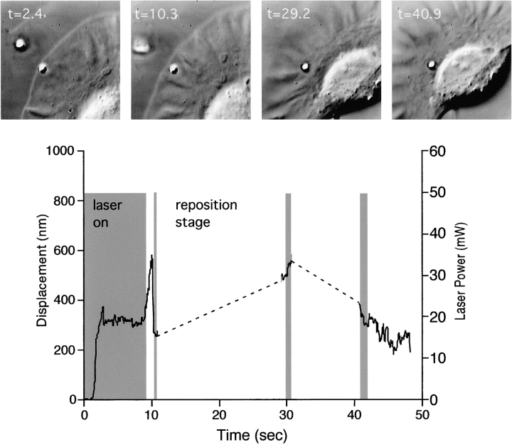
We asked whether the regional differences in binding of FN-coated beads (Fig. 6) correlated with differences in the traction forces exerted by the leading edge, compared with other regions of the lamella. To measure the strength of cytoskeletal attachment and force generation against the bead, we tested for reinforcement of the fibronectin beads (Choquet et al. 1997). A laser trap was used to place and hold FN-coated beads near the leading edge of the cell. When placed on the cell at this location, the beads frequently escaped the restraining force of the trap (Fig. 8t = 9 s). We then tried to recapture the beads into the center of the trap to determine if the force exerted on the bead by the cytoskeleton was less than or greater than that exerted by the trap. If the strength of the force exerted on the bead by the cytoskeleton was greater than the force exerted by the trap, then we could not recapture the bead, and the linkage between the bead and the cytoskeleton was considered to be reinforced. This response frequently (∼80%) occurred when FN-coated beads were placed on 3T3 fibroblasts (Choquet et al. 1997); however, as shown by the rapid displacement of the bead when the trap was turned on (Fig. 8t = 10.3 s), beads could easily be recaptured near the edge of the keratocyte lamella (100%, n = 10). Further into the lamella, at the region where it thickens, beads frequently (67%, n = 12) could not be recaptured (Fig. 8t = 29.2 s), and beads could also not be recaptured in the perinuclear region (Fig. 8t = 40.9 s). Control experiments in which beads were continuously recaptured in the front of the lamella indicate that this phenomenon is a function of location, not a function of the number of times that a recapture is attempted. Thus, there appears to be a positional reinforcement of the linkage between the bead and the cytoskeleton as the bead travels into the lamella.
Figure 8.
Beads that escape the force of a laser trap are more likely to be recaptured before they reach the thickened region of the lamella. A 50-mW laser trap was used to place and hold a 1-μm bead coated with FNIII 7–10 on the lamella. The bead was more likely to escape the trap if it was initially placed on the cell edge (t = 2.4 s). The same power trap could easily recapture the bead in the thin region of the lamella, as indicated by the sharp change in bead position (t = 10.3 s). However, the bead could not be recaptured if it reached the thickened region of the lamella (t = 29.9 s) or the nucleus.
To determine if this positional reinforcement could be due to an increase in cytoskeletal density rather than an enhancement of the linkage, keratocytes were labeled with Oregon green phalloidin, and the intensity of fluorescence from the leading edge to the perinuclear region was determined (Fig. 9). Similar to the results shown by others (Small et al. 1995), we observed a decrease in fluorescence between the front and the perinuclear region of the lamella, with the fluorescence intensity in the perinuclear region being ∼75% of the intensity at the leading edge. Since we were able to recapture beads located above the region where the actin cytoskeleton is the densest, the positional reinforcement is probably not completely due to entanglement with the underlying cytoskeleton, but rather an enhanced integrin–cytoskeletal linkage.
Figure 9.
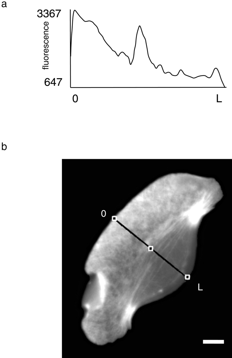
Density of F-actin in the keratocyte lamella. a, A line intensity histogram of a phalloidin-labeled keratocyte shows that the density of the F-actin network decreases away from the leading edge. The density increases again to ∼75% of its maximal value in the perinuclear region. b, Oregon green phalloidin-labeled keratocyte. Bar, 10 μm.
Discussion
The definition of traction forces at a subcellular level has uncovered several new aspects of the motile machinery in keratocytes that were unexpected. Propulsive forces are generated by the keratocyte lamella. The myosin-dense perinuclear region of the lamella is the major propulsive force-generating region. The thin leading edge of the lamella does not generate substantial forces, but it does act as a region of preferential binding between the rearward moving cytoskeleton and the ECM. Furthermore, the similarity in propulsive force per unit area generated against a submicron bead contact on both the dorsal surface and a portion of the ventral surface suggests that traction forces are generated by a similar mechanism on subcellular regions of both cell surfaces in the keratocyte. These findings indicate a possible mechanism of migration where traction forces are generated by a myosin-based, actin network condensation.
Comparison of Dorsal and Ventral Traction Forces
The largest ventral traction forces generated by the fish keratocyte lamella were ∼4.5 nN. This force yields a traction force per unit area of 0.2 nN/μm2. Although early measurements with deformable substrata were unable to detect this force on the ventral surface (Lee et al. 1994; Oliver et al. 1995), in later studies, the lamella of some cells appear to have rearward and forward directed traction forces (Oliver et al. 1999). The laser trap and the micromachined substratum measure forces generated in subcellular regions, without the influence of other forces exerted on the substratum. Because both of these methods measure rearward forces of roughly the same magnitude in the front lamella, we conclude that rearward directed forces are generated in the lamella of keratocytes, and these forces are similar to those observed in fibroblasts.
Our measurement of dorsal traction forces per unit area yields a traction force per unit area of 0.4 ± 0.3 nN/μm2 (n = 7, ± SD). The largest possible source of variability in determining this number comes from the measurement of the contact area between the bead and the cell. Our estimate is based on the contact area during initial placement of the bead with the laser trap, and this height could vary during the course of the experiment. However, other studies that have evaluated out method for determining the z-position of a bead by noting the change in the area of a DIC image of a bead suggest that it is accurate within ±20 nm (Suzuki, K.W., R.W. Sterba, and M.P. Sheetz, manuscript submitted for publication). This accuracy in height is within 15% of our area calculation and significantly less than our SD.
The agreement between dorsal and ventral traction forces in the keratocyte lamella suggests that a similar mechanism of force generation operates on both cell surfaces, and it is in contrast to the disagreement between ventral (Galbraith and Sheetz 1997) and dorsal traction forces (Felder and Elson 1990) measured in locomoting fibroblasts. Although the normalized ventral traction force generated by the lamella is in good agreement for both keratocytes and fibroblasts, the normalized dorsal traction forces measured in fibroblasts are two orders of magnitude smaller. There are several explanations for this discrepancy. The dorsal measurements on fibroblasts were made with a microneedle contacting the cell surface, and it is unclear what the area of contact is between the needle and the cell. Alternatively, the variations in the cytoskeletal structure between the ventral and dorsal surfaces of fibroblasts could account for the different forces measured on these two surfaces. The former explanation is more likely since studies (Heidemann et al. 1999) examining the forces that a fibroblast can exert against an extension of the cell created by attaching a needle to the cell and pulling, are of a similar magnitude, but different time course than those observed in this study.
Keratocytes Have a Receptor that Links FN to the Rearward Moving Cytoskeleton
Our results indicate that keratocytes use an FN receptor for adhesion to their substrata and for linking ECM to the rearward moving cytoskeleton. Other investigators have used immunofluorescence to demonstrate that keratocytes have a β1 integrin (Lee and Jacobson 1997), part of the α5β1 heterodimer of the fibronectin receptor. It has also been shown, by peptide and antibody competitive inhibition, that moving keratocytes have RGD and β1 dependent adhesion and locomotion (de Beus and Jacobson 1998). We have demonstrated that keratocytes use an FN receptor to generate preferential adhesions at the leading edge, and this receptor-ligand interaction allows the cytoskeleton to exert traction forces against the substratum for migration.
The preferential leading edge binding that we report for FN receptor–ligand interaction has also been observed in other cell types. In fibroblasts, there was a preferential attachment to the cytoskeleton of FN-coated beads at the leading edge (Nishizaka et al. 1999), but there was no preferential localization of FN-receptor at the leading edge. Similarly, in keratocytes, Concanavalin A–coated beads attached to the cytoskeleton when brought to the leading edge, but there was no preferential localization of Concanavalin A at the leading edge, as judged by immunofluorescence (Kucik et al. 1991). These results suggest that preferential binding at the leading edge could be due to something other than receptor localization, perhaps due to an avidity change caused by receptor cross-linking to the cytoskeleton. Alternatively, the curvature of the membrane at the leading edge could cause greater binding, but our inability to see a preferential binding at the leading edge with BSA-coated beads indicates that this is probably not the mechanism responsible for our results. The enhanced localization of β1 integrin, which we observe at the leading edge of keratocytes, suggests that receptor localization is at least partly responsible for the enhanced binding of FN-coated beads to the rearward moving cytoskeleton at the leading edge of keratocytes.
Variation in Traction Force Across the Lamella
Although the leading edge is a site of enhanced attachment of ECM to the force generating cytoskeleton, it is not a site of enhanced force generation. Our measurements of the ventral traction force (Fig. 3) demonstrated that force increased in magnitude with distance from the leading edge. Additionally, measurements of the dorsal traction variation using the positional reinforcement assay (Fig. 7) demonstrated that it was more difficult to recapture a bead as it traveled rearward, away from the leading edge of the lamella, suggesting that a stronger link was formed, enabling the cell to exert greater force against the bead. The ability to recapture a bead was not related to the number of times that we attempted to retrap the bead (data not shown). Nor was it related to the distance traveled across the lamella as beads that escaped the trap could be brought back to the front of the cell, allowed to escape again, and retrapped again. These results indicate that the cell generates larger traction forces in the thickened lamella and the perinuclear region. Furthermore, the location-specific traction forces did not correlate with the density of the underlying actin cytoskeleton. Low traction forces and easily retrapped beads were characteristic of the region of the lamella near the leading edge, an area of high F-actin concentration (Fig. 9). However, the myosin II density increase from the leading edge to the perinuclear region in the keratocyte lamella (Svitkina et al. 1997) correlates with the increase in traction force from the leading edge to the perinuclear region that we report. Thus, the magnitude of the traction force appears to be dependent upon the density of myosin II, suggesting that the cytoskeleton is a dynamic structure in which the linkages are dynamic force-generating components. Perhaps, myosin filaments cross-link actin filaments to create a cytoskeletal network that would generate a contractile force in proportion to the density of active myosin.
Models of Migration for the Fish Keratocyte
Several models have been proposed for explaining the migration of keratocytes: adhesion–propulsion (Oliver et al. 1999), network condensation (Evans 1993), and dynamic network contraction (Svitkina et al. 1997). None of the models are able to describe both of the key features of our traction force data: a rearward force in the lamella that increases with distance from the leading edge and a change in force direction in the perinuclear region. Therefore, we propose a new model that reconciles our observations and the observations that led to the previous models.
The adhesion–propulsion model (Oliver et al. 1999) suggests that the adhesive and the propulsive forces driving migration are equal and opposite, and there are no traction forces along the direction of migration. The only forces powering movement in that model are the large forces on either side of the nucleus that are oriented perpendicular to the direction of migration. These forces, which are approximately threefold larger than the lamella forces, are important in keratocyte migration. However, the adhesion–propulsion model, which only predicts net forces perpendicular to the direction of migration, cannot account for the rearward lamella traction forces that we measure on both the dorsal and the ventral surfaces. Furthermore, the rearward forces that we measure are not completely balanced by forces resisting motion since we are able to measure them over the small spatial region of the pad in the micromachined device.
The network condensation model (Evans 1993) proposes that the balance between polymerization of actin at the front of the cell and depolymerization at the rear drives the cell forward. Therefore, the network appears to move rearward in front of the cell, forward in the rear of the cell, and is stationary at a point in the lamella where the network's velocity equals the cell's velocity. The dynamic network contraction model (Svitkina et al. 1997) proposes that the force for forward movement is generated by contraction of an actin–myosin II network in the perinuclear region. As the actin and myosin contract, they form bundles that are oriented perpendicular to the direction of migration; the actin and myosin in this region move forward relative to the lamella and pull the cell body forward. Both models predict a change in traction force direction in the transition zone, which we observe experimentally. However, neither model can explain the increase in traction force that occurs between the leading edge and the perinuclear region of the lamella, nor can they account for the strong inward traction forces located on either side of the nucleus.
Model of Migration
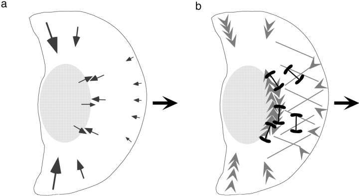
A model of keratocyte migration must account for the pattern of traction forces. The model needs to explain the rearward traction force in the lamella that increases in magnitude from the leading edge to the perinuclear region where it changes direction, and the model must provide a mechanism for generating the strong inward traction forces located on either side of the nucleus. We propose a model in which the actin–myosin condensation in the perinuclear region (Svitkina et al. 1997) generates the rearward traction forces under the lamella and forward movement of the cell body (Fig. 10). This mechanism is different from the dynamic network contraction model because it postulates that the condensing myosin pulls on the orthogonal array of lamella actin that is stationary with respect to the substratum. Support for this model comes from the polarity of the peripheral lamella actin (Svitkina et al. 1997) indicating that it could generate a rearward force, the continuity of the lamella actin with the condensed perinuclear fibers (Svitkina et al. 1997), and the magnitude of the traction force correlating well with the density of the myosin clusters. The proposed model also suggests that the forces generated in the condensation region are responsible for the change in traction force direction. The lamella generates rearward traction forces, and the periodic contractions of the condensation zone (Waterman-Storer, C., unpublished results) may exert sufficient force to pull the rear of the cell forward. Finally, the condensed perinuclear bundles probably generate the large forces on either side of the nucleus that are oriented perpendicular to the direction of migration. The perinuclear bundles are organized with their barbed ends oriented toward the cell periphery (Svitkina et al. 1997), which is the correct organization for myosin to generate the strong traction forces that are orthogonal to the direction of migration. These traction forces need to be stronger than the lamella traction forces to overcome the tighter adhesions to the substratum in these regions (Lee and Jacobson 1997). Moreover, the mixed polarity of these filaments in the center of the cell indicates that the mechanism of actin–myosin interaction is not sarcomeric, but is a contraction similar to that used to move fibroblasts on their ventral actin filaments (Cramer et al. 1997; Galbraith and Sheetz 1997). Thus, the condensation of actin and myosin in the perinuclear region may provide the force necessary for rearward lamellar traction force while organizing the longitudinal fibers that generate the traction forces orthogonal to the direction of migration.
Figure 10.
Model of keratocyte migration. Actin–myosin condensation in the perinuclear region generated rearward traction forces in the lamella by pulling on the orthogonal actin in this region. The condensation also generates forward forces that push the cell body forward. Finally, the perinuclear bundles generate the pincer forces that are orthogonal to the direction of migration. a, Orientation of traction forces measured by micromachined substrata and optical gradient trap. b, Orientation of actin and myosin network in keratocyte cytoskeleton (based on data from Svitkina et al. 1997).
Similarities between Traction Forces in Fibroblasts and Keratocytes
Our measurements of the traction forces generated by subcellular regions of slow moving fibroblasts (Galbraith and Sheetz 1997) and fast moving keratocytes have some similar features, suggesting that there is some commonality to portions of the mechanism of motility for both cell types. In the lamella of both cell types, there is a small retrograde force, the actin remains fixed with respect to the substratum (Verkhovsky et al. 1995; Cramer et al. 1997; Svitkina et al. 1997), and myosin II contracts and organizes the actin network (Verkhovsky et al. 1995; Svitkina et al. 1997). Myosin moves rearward relative to the substratum in fibroblasts, but it does not move rearward in keratocytes unless the rear of the cell is tethered to the substratum or another cell, suggesting that a similar mechanism may generate the rearward lamella force in both cells, especially when the adhesions to the surface are comparable.
The ventral actin fibers in fibroblasts and the perinuclear actin bundles in keratocytes are similarly organized. Both sets of fibers have their barbed ends oriented outward toward the cell periphery and have mixed polarity in the center. However, the ventral fibers in a fibroblast are oriented along the axis of migration, and the perinuclear bundles are oriented perpendicular to the direction of motion. This orientation of the actin bundles reflects the orientation of the maximum traction forces in both cell types. Additionally, when keratocytes become tethered to the substratum in their rear, they adopt the trigonal morphology observed in migrating fibroblasts, and their nucleus rotates 90° so that its long axis is parallel to the direction of migration (Galbraith, C., and M. Sheetz. 1997. Mol. Biol. Cell. 8:385). The keratocytes then exert strong forward directed traction forces underneath the tethered rear (Galbraith, C., and M. Sheetz. 1997. Mol. Biol. Cell. 8:385; Oliver et al. 1999) that are comparable to those exerted by fibroblasts (Galbraith and Sheetz 1997). If the keratocyte perinuclear fibers rotate with the nucleus, then the ventral actin polarity, barbed ends facing the cell periphery and mixed polarity in the center of the cell under the nucleus, would be the same for both cell types, allowing the keratocyte to move forward with a contraction mechanism that is similar to that used in fibroblasts (Galbraith and Sheetz 1997). The similarity in the amount of force generated by keratocyte and fibroblast lamella, and in the adhered tails of both cells suggests that this scheme may be possible. Therefore, we suggest that myosin contraction on the actin cytoskeleton–integrin–fibronectin links provide a dynamic tension that is responsive to both the sites of greatest adhesion and the formation of new links.
Acknowledgments
The authors wish to thank Dave Koester (MCNS, Research Triangle Park, NC) for his work on the micromachined device. We also thank Dan Felsenfeld and Jim Galbraith for critically reviewing this manuscript and offering suggestions throughout the study.
This work was supported by grants from the Office of Naval Research (N00014-97-0911) and the National Institutes of Health (GM 36277-15).
Footnotes
Abbreviations used in this paper: ECM, extracellular matrix; FN, fibronectin; t, time; VN, vitronectin.
References
- Burton K., Taylor D.L. Traction forces of cytokinesis measured with optically modified elastic substrata. Nature. 1997;385:450–454. doi: 10.1038/385450a0. [DOI] [PubMed] [Google Scholar]
- Choquet D., Felsenfeld D.P., Sheetz M.P. Extracellular matrix rigidity causes strengthening of integrin–cytoskeleton linkages. Cell. 1997;88:39–48. doi: 10.1016/s0092-8674(00)81856-5. [DOI] [PubMed] [Google Scholar]
- Cooper M.S., Schliwa M. Motility of cultured fish epidermal cells in the presence and absence of direct current electric fields. J. Cell Biol. 1986;102:1384–1399. doi: 10.1083/jcb.102.4.1384. [DOI] [PMC free article] [PubMed] [Google Scholar]
- Cramer L.P., Siebert M., Mitchison T.J. Identification of novel graded polarity actin filament bundles in locomoting heart fibroblastsimplications for the generation of motile force. J. Cell Biol. 1997;136:1287–1305. doi: 10.1083/jcb.136.6.1287. [DOI] [PMC free article] [PubMed] [Google Scholar]
- de Beus E., Jacobson K. Integrin involvement in keratocyte locomotion. Cell Motil. Cytoskel. 1998;41:126–137. doi: 10.1002/(SICI)1097-0169(1998)41:2<126::AID-CM4>3.0.CO;2-C. [DOI] [PubMed] [Google Scholar]
- Dembo M., Wang Y.L. Stresses at the cell-to-substrate interface during locomotion of fibroblasts. Biophys. J. 1999;76:2307–2316. doi: 10.1016/S0006-3495(99)77386-8. [DOI] [PMC free article] [PubMed] [Google Scholar]
- Euteneuer U., Schliwa M. Persistent, directional motility of cells and cytoplasmic fragments in the absence of microtubules. Nature. 1984;310:58–61. doi: 10.1038/310058a0. [DOI] [PubMed] [Google Scholar]
- Evans E. New physical concepts for cell amoeboid motion. Biophys. J. 1993;64:1306–1322. doi: 10.1016/S0006-3495(93)81497-8. [DOI] [PMC free article] [PubMed] [Google Scholar]
- Felder S., Elson E.L. Mechanics of fibroblast locomotionquantitative analysis of forces and motions at the leading lamellas of fibroblasts. J. Cell Biol. 1990;111:2513–2526. doi: 10.1083/jcb.111.6.2513. [DOI] [PMC free article] [PubMed] [Google Scholar]
- Felsenfeld D.P., Choquet D., Sheetz M.P. Ligand binding regulates the directed movement of beta1 integrins on fibroblasts. Nature. 1996;383:438–440. doi: 10.1038/383438a0. [DOI] [PubMed] [Google Scholar]
- Felsenfeld D., Schwartzberb P., Venegas A., Tse R., Sheetz M. Selective regulation of integrin–cytoskeleton interactions by the tyrosine kinase Src. Nat. Cell Biol. 1999;1:200–206. doi: 10.1038/12021. [DOI] [PubMed] [Google Scholar]
- Galbraith C.G., Sheetz M.P. A micromachined device provides a new bend on fibroblast traction forces. Proc. Natl. Acad. Sci. USA. 1997;94:9114–9118. doi: 10.1073/pnas.94.17.9114. [DOI] [PMC free article] [PubMed] [Google Scholar]
- Galbraith C.G., Sheetz M.P. Forces on adhesive contacts affect cell function. Curr. Opin. Cell Biol. 1998;10:566–571. doi: 10.1016/s0955-0674(98)80030-6. [DOI] [PubMed] [Google Scholar]
- Gelles J., Schnapp B.J., Sheetz M.P. Tracking kinesin-driven movements with nanometre-scale precision. Nature. 1988;331:450–453. doi: 10.1038/331450a0. [DOI] [PubMed] [Google Scholar]
- Harris A.K., Wild P., Stopak D. Silicone rubber substrataa new wrinkle in the study of cell locomotion. Science. 1980;208:177–179. doi: 10.1126/science.6987736. [DOI] [PubMed] [Google Scholar]
- Heidemann S.R., Kaech S., Buxbaum R.E., Matus A. Direct observations of the mechanical behaviors of the cytoskeleton in living fibroblasts. J. Cell Biol. 1999;145:109–122. doi: 10.1083/jcb.145.1.109. [DOI] [PMC free article] [PubMed] [Google Scholar]
- Kucik D.F., Kuo S.C., Elson E.L., Sheetz M.P. Preferential attachment of membrane glycoproteins to the cytoskeleton at the leading edge of lamella. J. Cell Biol. 1991;114:1029–1036. doi: 10.1083/jcb.114.5.1029. [DOI] [PMC free article] [PubMed] [Google Scholar]
- Lauffenburger D.A., Horwitz A.F. Cell migrationa physically integrated molecular process. Cell. 1996;84:359–369. doi: 10.1016/s0092-8674(00)81280-5. [DOI] [PubMed] [Google Scholar]
- Lee J., Jacobson K. The composition and dynamics of cell–substratum adhesions in locomoting fish keratocytes. J. Cell Sci. 1997;110:2833–2844. doi: 10.1242/jcs.110.22.2833. [DOI] [PubMed] [Google Scholar]
- Lee J., Leonard M., Oliver T., Ishihara A., Jacobson K. Traction forces generated by locomoting keratocytes. J. Cell Biol. 1994;127:1957–1964. doi: 10.1083/jcb.127.6.1957. [DOI] [PMC free article] [PubMed] [Google Scholar]
- Lin C.H., Espreafico E.M., Mooseker M.S., Forscher P. Myosin drives retrograde F-actin flow in neuronal growth cones. Biol. Bull. 1997;192:183–185. doi: 10.2307/1542600. [DOI] [PubMed] [Google Scholar]
- Marcantonio E.E., Hynes R.O. Antibodies to the conserved cytoplasmic domain of the integrin β1 subunit react with proteins in vertebrates, invertebrates, and fungi. J. Cell Biol. 1988;106:1765–1772. doi: 10.1083/jcb.106.5.1765. [DOI] [PMC free article] [PubMed] [Google Scholar]
- Mitchison T.J., Cramer L.P. Actin-based cell motility and cell locomotion. Cell. 1996;84:371–379. doi: 10.1016/s0092-8674(00)81281-7. [DOI] [PubMed] [Google Scholar]
- Nishizaka T., Shi Q., Sheetz M.P. Position dependent linkages of fibronectin–integrin–cytoskeleton. Proc. Natl. Acad. Sci. USA. 1999;In press. doi: 10.1073/pnas.97.2.692. [DOI] [PMC free article] [PubMed] [Google Scholar]
- Oliver T., Dembo M., Jacobson K. Traction forces in locomoting cells. Cell Motil. Cytoskel. 1995;31:225–240. doi: 10.1002/cm.970310306. [DOI] [PubMed] [Google Scholar]
- Oliver T., Dembo M., Jacobson K. Separation of propulsive and adhesive traction stresses in locomoting keratocytes. J. Cell Biol. 1999;145:589–604. doi: 10.1083/jcb.145.3.589. [DOI] [PMC free article] [PubMed] [Google Scholar]
- Pierschbacher M.D., Ruoslahti E. Influence of stereochemistry of the sequence Arg-Gly-Asp-Xaa on binding specificity in cell adhesion. J. Biol. Chem. 1987;262:17294–17298. [PubMed] [Google Scholar]
- Regen C.M., Horwitz A.F. Dynamics of β1 integrin-mediated adhesive contacts in motile fibroblasts. J. Cell Biol. 1992;119:1347–1359. doi: 10.1083/jcb.119.5.1347. [DOI] [PMC free article] [PubMed] [Google Scholar]
- Ruoslahti E., Hayman E.G., Pierschbacher M., Engvall E. Fibronectinpurification, immunochemical properties, and biological activities. Methods Enzymol. 1982;82:803–831. doi: 10.1016/0076-6879(82)82103-4. [DOI] [PubMed] [Google Scholar]
- Schliwa M., van Blerkom J. Structural interaction of cytoskeletal components. J. Cell Biol. 1981;90:222–235. doi: 10.1083/jcb.90.1.222. [DOI] [PMC free article] [PubMed] [Google Scholar]
- Schmidt C.E., Horwitz A.F., Lauffenburger D.A., Sheetz M.P. Integrin–cytoskeletal interactions in migrating fibroblasts are dynamic, asymmetric, and regulated. J. Cell Biol. 1993;123:977–991. doi: 10.1083/jcb.123.4.977. [DOI] [PMC free article] [PubMed] [Google Scholar]
- Small J.V., Herzog M., Anderson K. Actin filament organization in the fish keratocyte lamellipodium. J. Cell Biol. 1995;129:1275–1286. doi: 10.1083/jcb.129.5.1275. [DOI] [PMC free article] [PubMed] [Google Scholar]
- Sterba R., Sheetz M. Basic laser tweezers. In: Sheetz M., editor. Laser Tweezers in Cell Biology. Academic Press; San Diego, CA: 1998. pp. 29–41. [PubMed] [Google Scholar]
- Svitkina T.M., Verkhovsky A.B., McQuade K.M., Borisy G.G. Analysis of the actin–myosin II system in fish epidermal keratocytesmechanism of cell body translocation. J. Cell Biol. 1997;139:397–415. doi: 10.1083/jcb.139.2.397. [DOI] [PMC free article] [PubMed] [Google Scholar]
- Svoboda K., Block S. Biological applications of optical forces. Annu. Rev. Biophys. Biomol. Struct. 1994;23:247–285. doi: 10.1146/annurev.bb.23.060194.001335. [DOI] [PubMed] [Google Scholar]
- Theriot J.A., Mitchison T.J. Actin microfilament dynamics in locomoting cells. Nature. 1991;352:126–131. doi: 10.1038/352126a0. [DOI] [PubMed] [Google Scholar]
- Verkhovsky A.B., Svitkina T.M., Borisy G.G. Myosin II filament assemblies in the active lamella of fibroblaststheir morphogenesis and role in the formation of actin filament bundles. J. Cell Biol. 1995;131:989–1002. doi: 10.1083/jcb.131.4.989. [DOI] [PMC free article] [PubMed] [Google Scholar]
- Wang N., Butler J.P., Ingber D.E. Mechanotransduction across the cell surface and through the cytoskeleton. Science. 1993;260:1124–1127. doi: 10.1126/science.7684161. [DOI] [PubMed] [Google Scholar]


