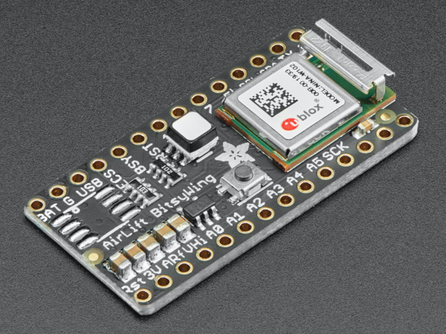
The ItsyBitsy M0 Express has BAT G USB on the top left, right next to the micro USB port
These pins are:
- BAT - battery input for an alternative power source to USB, the voltage can only be from 3.5V to 6VDC
- G (GND) - Power/data ground
- USB - This is the same pin as the MicroUSB connector's 5V USB power pin. This should be used as an output to get 5V power from the USB port. Say if you need to power a bunch of NeoPixels or servos.
You can always put any voltage you like into BAT and the circuitry will switch between BAT and USB dynamically for you. That means you can have a Batter backup that only gets enabled when USB is disconnected.
If you want to add rechargeable power, a LiPoly Backpack Add-on can be soldered into these three pins that will let you have a battery that is automatically recharged whenever USB is plugged in, then switches to LiPoly when on the go:

In addition to the three standard power pins, the ItsyBitsy M0 Express has a few more pins available for power sourcing:
- 3V - this is the regulated output from the onboard regulator. You can draw 500mA whether powered by USB or battery.
- Vhi - this is a special pin! It is a dual-Schottkey-diode connected output from BAT and USB. This means this will always have the higher-of-the-two voltages, but will always have power output. The voltage will about 5VDC when powered by USB, but can range from 3.5-6VDC when powered from battery. It's not regulated, but it is high-current, great for driving servos and NeoPixels.
- EN - connected to the regulator enable, it will let you shut off power - when running on battery only. But at least you don't have to cut a trace or wire to your battery. This pin does not affect power when using USB
Logic pins
This is the general purpose I/O pin set for the microcontroller. All logic is 3.3V. You can usually use 3V logic as an input to 5V, but the 3V Itsy pins should not be connected to 5V!
Nearly all pins can do PWM output
All pins except #4 can be interrupt inputs

Along the top edge:
- #0 / RX - GPIO #0, also receive (input) pin for Serial1. This pin can also be an analog input (Analog #20) or I2S LRCLK
- #1 / TX - GPIO #1, also transmit (output) pin for Serial1. This pin can also be an analog input (Analog #21) or I2S bitclock
- SDA and SCL - these are the I2C hardware interface pins. There's no pull up on this pin by default so when using with I2C, you may need a 2.2K-10K pullup on each to 3.3V
- #5 - GPIO #5, can also do PWM output. Pin #5 is labeled as "5!" because it is a special OUTPUT-only pin: it is level-shifted up to Vhi voltage, so it's perfect for driving NeoPixels that want a ~5V logic level input. You can use this with our NeoPixel DMA control library to automatically write NeoPixel data without needing any processor time.
- #7 - GPIO #7, or I2S LRCLK
- #9 - GPIO #9, also analog input #25 and can do PWM output, or I2S data channel 0
- #10 - GPIO #10, can do PWM output.
- #11 - GPIO #11, can do PWM output.
- #12 - GPIO #12, or I2S data channel 0
- #13 - GPIO #13, can do PWM output and is connected to the red LED next to the Reset button

Along the bottom edge:
- A0 - This pin is analog input A0 but is also an analog output due to having a DAC (digital-to-analog converter). You can set the raw voltage to anything from 0 to 3.3V, unlike PWM outputs this is a true analog output
- A1 thru A5 - These are each analog input as well as digital I/O pins. A1 and A2 can do PWM output.
- SCK/MOSI/MISO - These are the hardware SPI pins, you can use them as everyday GPIO pins but recommend keeping them free as they are best used for hardware SPI connections for high speed.
Along the right edge:
- #2 - GPIO #2
- #3 - GPIO #3. Can also do PWM output and Analog #23, or I2S master clock
- #4 - GPIO #4. Can also do PWM output and Analog #22, or I2S data channel 1
- SWCLK & SWDIO - These are the debug-interface pins, used if you want to reprogram the chip directly or attach a debugger.
The following pins have hardware capacitive touch capability: A0, A1, A2, A3, A4, A5, and #9.
The following pins have analog input capability: A0, A1, A2, A3, A4, A5, #0, #1, #3, #4 and #9.
These pins are available in CircuitPython under the board module. Names that start with # are prefixed with D and other names are as is. So #0 / RX above is available as board.D0 and board.RX for example.
SPI Flash and DotStar
As part of the 'Express' series of boards, this ItsyBitsy is designed for use with CircuitPython. To make that easy, we have added two extra parts: a mini DotStar (RGB LED) and a 2 MB SPI Flash chip.

The DotStar is connected to pin #40 (clock) and #41 (data) in Arduino, so just use our DotStar library and set it up as a single-LED strand on pins 40 & 41. The DotStar is powered by the 3.3V power supply but that hasn't shown to make a big difference in brightness or color. The DotStar is also used by the bootloader to let you know if the device has enumerated correctly (green) or USB failure (red). In CircuitPython, the LED is used to indicate the runtime status.
In CircuitPython you can access it with something like dot = adafruit_dotstar.DotStar(board.APA102_SCK, board.APA102_MOSI, 1, brightness=0.5)
The SPI Flash is connected to 4 pins that are not brought out on the GPIO pads. This way you don't have to worry about the SPI flash colliding with other devices on the main SPI connection. Under Arduino, the FLASH SCK pin is #38, MISO is #36, MOSI is #37, and CS is #39. In Arduino, you'll be able to access the Flash SPI port under SPI1 - this is a fully new hardware SPI device separate from the GPIO pins on the outside edge of the board. In CircuitPython, the SPI flash is used natively by the interpreter and is read-only to user code, instead the Flash just shows up as the writeable disk drive!

- RST - this is the Reset pin, tie to ground to manually reset the microcontroller, as well as launch the bootloader manually
- ARef - the analog reference pin. Normally the reference voltage is the same as the chip logic voltage (3.3V) but if you need an alternative analog reference, connect it to this pin and select the external AREF in your firmware. Can't go higher than 3.3V!
Page last edited March 30, 2024
Text editor powered by tinymce.