Electronic Circuit Breaker
S8V-CP - Electronic Circuit Breaker
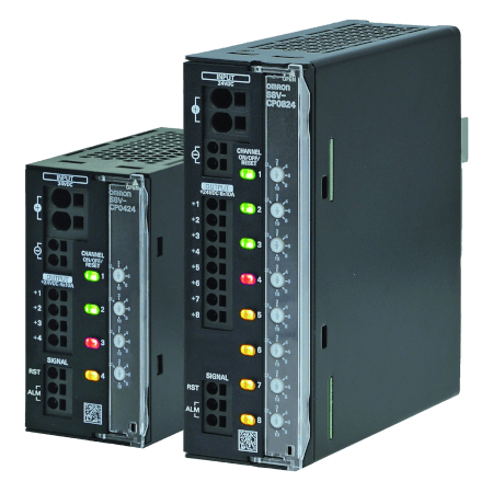
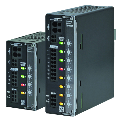
S8V-CP protects DC circuits very precisely. Overload and short circuits are accurately detected and reliably switched off
- 4- / 8-channel electronic circuit breakers with adjustable tripping currents from 2 to 10 A
- Thermomagnetic tripping characteristic
- Sequential and load-dependent start-up of the outputs to avoid high inrush currents
- Ability to switch-on high capacitive loads reliably
- Backlit buttons with multi-color LEDs indicate the output status at a glance
- Push-In Plus terminal blocks
- Space saving Value Design for Panel
- UL Class 2 model reduces the costs of applying a safety standard
Specifications & ordering info
Ordering information
Model Number Structure
Model Number Legend
Not all combinations are possible. Refer to List of Models in Ordering Information, below.

(1) Number of Outputs
| Code | Number of Outputs |
|---|---|
| 04 | 4 outputs |
| 08 | 8 outputs |
(2) Rated input voltage
| Code | Rated input voltage |
|---|---|
| 24 | 24 VDC |
(3) UL Class 2 output
| Code | UL Class 2 output certified |
|---|---|
| S | Yes |
| No | No |
List of Models
Unit
| Number of Outputs | UL Class 2 output | Order code |
|---|---|---|
| 4 outputs | No | S8V-CP0424 |
| Yes | S8V-CP0424S | |
| 8 outputs | No | S8V-CP0824 |
Specifications
| Item | Model Number of Outputs UL Class 2 output | S8V-CP0424 | S8V-CP0424S | S8V-CP0824 | |
|---|---|---|---|---|---|
| 4 | 4 | 8 | |||
| No | Yes | No | |||
| I/O characteristics | Rated input voltage (Input voltage allowable range) | 24 VDC (20 to 30 VDC) | 24 VDC (20 to 28.8 VDC) | 24 VDC (20 to 30 VDC) | |
| Allowable
input current
2
For power input terminals, use 35 A max. per pole. |
40 A | 15.2 A | 70 A | ||
| Max. rated output current (per output) | 10 A | 3.8 A | 10 A | ||
| Internal
voltage drop
2
A voltage drop will occur in the S8V-CP. Consider
the voltage drop at the output. |
200 mV max. | 150 mV max. | 200 mV max. | ||
| Output leakage current | 10 mA max. | ||||
| Power consumption
2
When
selecting the power supply, be sure to include the internal power
consumption of the S8V-CP and not just the power consumption of
the load. |
When all outputs are connected |
10 W max. (at 10 A) | 3.1 W max. (at 3.8 A) | 20 W max. (at 10 A) | |
| When all output branches are tripped |
0.84 W typ. | 0.82 W typ. | 1.32 W typ. | ||
| Start-up
time
2
Outputs start in order from +VO1 to +VO8. +VO1 starts after
the initialization time. Start-up delay time of each output is automatically
decided depending on the load. If the start-up delay time is over
5 s, the next output is forcibly started. |
Initialization time | 250 ms typical | |||
| Start-up delay time | 50 ms to 5 s | ||||
| Functions
2
Refer
to Cat. No. T226-E1 for details. |
Current
tripping function
2
Refer to Cat. No. T226-E1
for details. |
Rated output current | 2 A, 3 A, 4 A, 6 A, 8 A, 10 A | 3.8 A | 2 A, 3 A, 4 A, 6 A, 8 A, 10 A |
| Cutoff current | 2.5 A, 3.5 A, 4.5 A, 6.5 A, 8.5 A, 10.5 A |
3.8 A | 2.5 A, 3.5 A, 4.5 A, 6.5 A, 8.5 A, 10.5 A |
||
| Over voltage
tripping function
2
Refer to Cat. No. T226-E1
for details. |
No | Yes | No | ||
| Push button (ON/OFF/RESET) with indicator | Yes (LED colors: Red/Green/Yellow) | ||||
| Reset signal input (RST) | Yes (High level: 15 to 30 VDC, Low level: 0 to 5 VDC) | ||||
| Alarm signal output (ALM1/ALM2) | Yes (MOS FET relay output 30 VDC max., 50 mA max.) | ||||
| Insulation | Dielectric strength | 1.0 kVAC for 1 min (between all terminals and DIN rail mounting parts), current cutoff 20 mA | |||
| Insulation resistance | 100 MΩ min. (between all terminals and DIN rail mounting parts) at 500 VDC | ||||
| Environment | Ambient operating temperature | –25 to 70°C (Derating is required according to the temperature.) (with no condensation or icing) | |||
| Storage temperature | –40 to 85°C (with no condensation or icing) | ||||
| Ambient operating humidity | 5% to 96% (storage humidity: 5% to 96%) | ||||
| Vibration resistance | 10 to 55 Hz, maximum 5 G, 0.42 mm half amplitude for 2 h each in X, Y, and Z directions | ||||
| Shock resistance | 294 m/s2, 3 times each in ±X, ±Y, ±Z directions | ||||
| Reliability | MTBF
2
MTBF
is calculated according to JEITA RCR-9102. |
13,5000 hrs typ. | 60,000 hrs typ. | 13,5000 hrs typ. | |
| Life expectancy
2
Refer
to Cat. No. T226-E1 for details. |
10 years min. | ||||
| Construction | Weight | 160 g max. | 170 g max. | 420 g max. | |
| Cooling fan | No | ||||
| Degree of protection | IP20 by EN/IEC 60529 | ||||
| Standards | EMI | Conforms to EN 61000-6-3 | |||
| EMS | Conforms to EN 61000-6-2 | ||||
| Safety standards | UL 508 (CSA22.2 No.14-10) Listing Pol2 UL 2367 Recognition (Max. 100W per output, per Class 2 limitations) Pol2
2
UL Class 2 output applies for the S8V-CP0424S model only. CE (EN 61000-6-2, EN 61000-6-3) |
||||
How can we help you?
If you have a question or would like to ask for a quote, please contact us or send a request.
Contact Our Experts Electronic Circuit Breaker
Thank you for submitting your request. We will come back to you as soon as possible.
We are experiencing technical difficulties. Your form submission has not been successful. Please accept our apologies and try again later. Details: [details]
DownloadQuotation for Electronic Circuit Breaker
By completing this form you can request a quotation. Your personal details will be handled confidentially.

Thank you for requesting a quotation. We will provide you with the required information as soon as possible.
We are experiencing technical difficulties. Your form submission has not been successful. Please accept our apologies and try again later. Details: [details]
Download