#ILI9341 / ILI9486 / ILI9488 LCD driver for ESP8266
Fast LCD driver written from scratch for ESP8266 for driving ILI9341 (240x320) or ILI9486 / ILI9488 (320x480) compatible LCD controllers using 4-wire SPI interface. ESP8266's HSPI interface is used (full 16 x 32-bit buffer). There's also option for full SW bit-banging (for any GPIOs, but it's slower than HSPI. Use HSPI whenever possible).
Maximum effort was taken to create a fast driver, because managing 480x320 pixels over 4-wire SPI is timing critical (just pixel data to fill whole 480x320 screen will take 2.46 Mbit for 16 bpp color depth mode (65k colors) and 3.69 Mbit for 18 bpp color depth mode (262k colors, 24 bits per one pixel are used, last two bits from each byte are ignored by LCD controller) and we need to clock out this amount of bits in a fraction of second over the serial line)
Two versions are available:
- for ESP8266_NONOS_SDK 2.0.0
- for ESP8266_RTOS_SDK 1.5.0
ESP8266 @ 80 MHz with 2.4" LCD module (320x240, 16 bpp, HSPI CLK 40 MHz) - video
[](http://www.youtube.com/watch?v=E9Ds4IS-Ndk)
ESP8266 @ 80 MHz with hacked 3.5" KeDei LCD module v4.0 (480x320, 16 bpp, HSPI CLK 40 MHz) - video
[](http://www.youtube.com/watch?v=7dyVdiZUw1o)
ESP8266 @ 80 MHz with ER-TFT035-6 - 3.5" LCD module from www.buydisplay.com (480x320, 18 bpp, HSPI CLK 40 MHz) - video
[](http://www.youtube.com/watch?v=X0mwfAqiqkc)
##Connection with LCD controller
4-wire SPI interface (5-wire with optional SDO line) => ILI9341's IM[3:0] = 1110 / ILI9488's IM[2:0] = 111
 ---------------------------        VDD   ----------------------------------
|          ESP8266          |        |   |          LCD controller          |
|          (master)         |        `->-| #RST         (slave)             |
|                           |            |                                  |
|       MTDO/GPIO15/HSPI_CS |------>-----| #CS (active L)                   |
|     MTCK/GPIO13/HSPI_MOSI |------>-----| SDI/SDA                          |
|     MTDI/GPIO12/HSPI_MISO |- - - <- - -| SDO (optional, see WLCD_NO_READ) |
|      MTMS/GPIO14/HSPI_CLK |------>-----| >SCL (rising edge)               |
|                     GPIO4 |------>-----| D/#C (data H / command L)        |
|                           |            |                                  |
|                           |            | (for other pins see PDF manual)  |
 ---------------------------              ----------------------------------
SPI interface
If WLCD_USE_HSPI is defined (fast, less CPU load):
- you can change only GPIOs for #CS and D/#C. The rest (HSPI controller) is hardwired inside ESP8266
- WLCD_SPI_CLK_PREDIV and WLCD_SPI_CLK_CNTDIV determines the speed of HSPI clock - configure properly / test to match your LCD controller specification
If WLCD_USE_HSPI is not defined (SW bit-banging, slower, bigger CPU load):
- you can change all GPIOs (see WLCD MAIN CONFIG section in wlcd.h)
- the speed is determined by the speed of the CPU (see wlcd_write8_sw(...) / wlcd_read8_sw(...))
##Main features
Hardware HSPI / SW bit-banging
In HSPI mode (WLCD_USE_HSPI is defined, fast, less CPU load) we're using ESP8266's HSPI hardware module.
You can choose the best suitable HSPI clock using WLCD_SPI_CLK_PREDIV and WLCD_SPI_CLK_CNTDIV (see "WLCD MAIN CONFIG" section in wlcd.h). Most of the displays are happy up to 40 MHz SPI clock (including), see YT videos on the top.
The whole 16 x 32-bit buffer (SPI_W0..15) is used for MISO/MOSI transactions and we're using 32-bit copy instructions to speed up the copy process. There's tradeoff because of that - if we're drawing image which is not RLE compressed (is just a continuous stream of pixels) and we're using HSPI mode, then image data buffer must be 4-bytes aligned (and allocated memory size must be multiples of 4), because we're using 32-bit copy. Copying of unaligned address would end up in "Fatal exception (9)" - "Attempt to load or store data at an address which cannot be handled due to alignment" according to XTENSA LX 106 datasheet. So we need to use STORE_ATTR ("__attribute__ ((aligned(4)))") prefix when declaring arrays passed as Buf. We can also use os_malloc(...) - at least on ESP8266 the os_malloc(...) also allocates 4-byte aligned arrays.
//all of these will produce pointer to MyBuf that's 4-bytes aligned.
uint8_t STORE_ATTR MyBuf[10*4];
uint32_t STORE_ATTR MyBuf[10];
uint8_t* MyBuf = (uint8_t*)os_malloc(10*4);
In SW bit-banging mode (WLCD_USE_HSPI is not defined, slower, bigger CPU load), all the GPIOs are managed by SW. This approach is significantly slower. It's implemented just for the critical situations when you've already used the ESP8266's pins GPIO13, GPIO12 (optional), GPIO14 for something else and you have no option to re-wire it to different GPIOs.
Color depth
Supported color depths are 16-bit (65k colors) / 18-bit (262k colors) per pixel (command 0x3A sets DBI[2:0] to 101 or 110).
Primary color depth is 16 bpp - use WLCD_16BPP for maximum speed (many optimizations take advance of the fact, that we can move exactly two pixels by one 32-bit move).
Note: ILI9488 doesn't support 16 bpp in SPI mode (DBI Type C mode), it supports
only 3 bpp (DBI[2:0] = 001) and 18 bpp (DBI[2:0] = 110). Ask ILItek why it was not implemented in ILI9488.
Compared to that, ILI9341 supports both 16 bpp and 18 bpp in SPI mode and it has only 320x240 pixels. Funny, that ILItek removed the faster way in more demanding controller.
Note2: in hacked 3.5" KeDei LCD module v4.0 we can use 16 bpp, because the real data input into ILI9488 is 8-bit parallel (IM[2:0] = 011). See my https://github.com/wdim0/esp8266_with_KeDei_lcd_module repo for details.
uint32_t Color and related macros
General meaning of Color parameter used in many functions is related to used WLCD_*BPP mode (see config section above).
It's uint32_t to make it universal for all color depths.
- if WLCD_BPP==WLCD_16BPP => Color is of wlcd_R5G6B5_struct structure / uint32_t filled by R5G6B5
- if WLCD_BPP==WLCD_18BPP => Color is of wlcd_R8G8B8_struct structure / uint32_t filled by R6G6B6 or R8G8B8 (R6G6B6 or R8G8B8 are the same - last two bits are ignored by the LCD controller)
Use WLCD_RGB_TO_COLOR(...) macro to get uint32_t Color using R, G, B 8-bit values.
Use WLCD_COLOR(...) macro to convert wlcd_R5G6B5_struct / wlcd_R5G6B5_struct to uint32_t Color.
Line drawing
Function for drawing a line is heavily optimized for speed (addition of fixed point with precalculations, repeating of preconfigured HSPI transaction, ...).
The speed-up is the more significant, the more the line is horizontal or vertical. Diagonal lines are
the slowest (there is no other way than to re-set drawing point for every pixel that's not in the same row/column).
WLCD images
Use wlcd_img_gen tool to generate WLCD images from 24-bit / 16-bit BMPs. WLCD image can be
RLE compressed (uses 8-bit counter). The wlcd_img_gen tool by default tries both ways
and decides what's smaller. To produce smaller images, try to avoid smooth color gradients.
WLCD images can be 16 bpp / 24 bpp and this setting must correspond to used WLCD_*BPP
- if WLCD_BPP==WLCD_16BPP => generate WLCD image with parameter --16bpp
- if WLCD_BPP==WLCD_18BPP => generate WLCD image with parameter --24bpp
See function wlcd_img_draw(...) for WLCD image format description
Fonts
Fonts are implemented using RREs - each letter is represented by rectangles (minimum count possible). This gives us speed, easy font zooming / making font bolder, ...
Fonts with code page 437 (USA, original IBM PC hardware) and code page 1250 (Central and East European Latin) included. If you need your own fonts / code pages, use fonter.c included as a starting point and assemble your own wlcd_font_*.h
Other features
Orientation can be changed in 0 / 90 / 180 / 270 degrees of rotation (see "WLCD MAIN CONFIG" section in wlcd.h).
Reading of display data (reading of LCD controller's GRAM) into WLCD image is implemented (optional conversion to R5G6B5 on the fly).
Demo / speed test of this driver is included (see user_main.c)
##Provided functions and macros
#if(WLCD_BPP==WLCD_16BPP)
	#define WLCD_RGB_TO_COLOR(R, G, B)	(  ((((uint16_t)(R))&0xF8)<<8) | ((((uint16_t)(G))&0xFC)<<3) | (((uint16_t)(B))>>3) ) //R, G, B -> R5G6B5
#else
	#define WLCD_RGB_TO_COLOR(R, G, B)	(  (((uint32_t)(R))<<16) | (((uint16_t)(G))<<8) | (B) ) //R, G, B -> R8G8B8
#endif
//
#define WLCD_COLOR(AnyColorStruct)		(*((uint32_t*)&AnyColorStruct)) //wlcd_*_struct -> uint32_t Color
//
#define WLCD_R8_TO_R5(R8)				(R8>>3)
#define WLCD_G8_TO_G6(G8)				(G8>>2)
#define WLCD_B8_TO_B5(B8)				(B8>>3)

int8_t ICACHE_FLASH_ATTR wlcd_init(void);
//
char* ICACHE_FLASH_ATTR wlcd_get_version(void);
//
void ICACHE_FLASH_ATTR wlcd_set_drawing_rect(uint16_t X, uint16_t Y, uint16_t Width, uint16_t Height);
void ICACHE_FLASH_ATTR wlcd_write_dup_color(uint32_t Color, uint32_t PixelCount);
#define wlcd_rect_fill(X, Y, Width, Height, Color)	do { \
	wlcd_set_drawing_rect((X), (Y), (Width), (Height)); \
	wlcd_write_dup_color((Color), (uint32_t)(Width)*(Height)); \
	} while (0)
#define wlcd_pixel_draw(X, Y, Color)		wlcd_rect_fill((X), (Y), 1, 1, (Color))	//! for continuous stream of pixels use wlcd_write_dup_color(...) / wlcd_rect_fill(...) / wlcd_img_draw(...)
void ICACHE_FLASH_ATTR wlcd_line_draw(int16_t X1, int16_t Y1, int16_t X2, int16_t Y2, uint32_t Color);
//
void ICACHE_FLASH_ATTR wlcd_img_get_info(uint8_t* ImgData, wlcd_img_info_struct* RetImgInfo);
#define wlcd_img_get_width(ImgData)				(((wlcd_img_info_struct*)ImgData)->Width)
#define wlcd_img_get_height(ImgData)			(((wlcd_img_info_struct*)ImgData)->Height)
#define wlcd_img_get_bpp_code(ImgData)			(((wlcd_img_info_struct*)ImgData)->BppCode) //see wlcd_img_bpp_enum
#define wlcd_img_is_rle_compressed(ImgData)		(((wlcd_img_info_struct*)ImgData)->IsRLECmprs)
void ICACHE_FLASH_ATTR wlcd_img_draw(uint8_t* ImgData, uint16_t X, uint16_t Y); //! if one of these is true: 1) the image is not RLE compressed and we're using HSPI (WLCD_USE_HSPI is defined) OR 2) the image is RLE compressed and image color depth is 24bpp, then => ImgData must be 4-bytes aligned and allocated memory length must be multiples of 4. (see wlcd_write_buf_hspibuf64(...) for details why)
uint32_t ICACHE_FLASH_ATTR wlcd_img_get(uint32_t* Buf, uint16_t X, uint16_t Y, uint16_t Width, uint16_t Height); //! if WLCD_USE_HSPI is defined, then Buf must be 4-bytes aligned and allocated memory length must be multiples of 4
//
//see wlcd_text_draw_settings_struct definition for more details
void ICACHE_FLASH_ATTR wlcd_text_draw_or_measure(char* Txt, wlcd_text_draw_settings_struct* S, uint8_t DontDrawJustMeasure, uint16_t* RetWidth, uint16_t* RetHeight);
#define wlcd_text_measure(Txt, S, RetWidth, RetHeight)	wlcd_text_draw_or_measure(Txt, S, 1, RetWidth, RetHeight)
#define wlcd_text_draw(Txt, S)							wlcd_text_draw_or_measure(Txt, S, 0, NULL, NULL)
uint16_t ICACHE_FLASH_ATTR wlcd_text_nchars_width(uint16_t NumOfChars, wlcd_text_draw_settings_struct* S);
uint16_t ICACHE_FLASH_ATTR wlcd_text_nrows_height(uint16_t NumOfRows, wlcd_text_draw_settings_struct* S);
(see wlcd.c for details)
##Installation, compilation, flashing
As a development IDE I'm using Eclipse on Win 7 with Espressif's NON-OS SDK (/ RTOS SDK) and my ESP8266 (ESP-07 or any other ESP-* module) is programmed using "FTDI FT232RL USB to TTL Serial Converter". So this installation guide is for those who have / want to have the same development IDE.
1] download "Unofficial Development Kit for Espressif ESP8266":
http://www.esp8266.com/viewtopic.php?t=820
(big thanks to Mikhail Grigorev / CHERTS)
If you follow the steps correctly, you have everything you need and everything works right out of the box
2] get familiar with Eclipse just a little bit. Try to compile & run at least "hello_world" or "blinky2" examples
3] download my "esp8266_fast_lcd_driver_hspi" repo as a zip file, unpack to some directory (let's suppose for example "c:\Espressif\devel\esp8266_fast_lcd_driver_hspi")
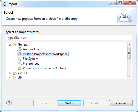
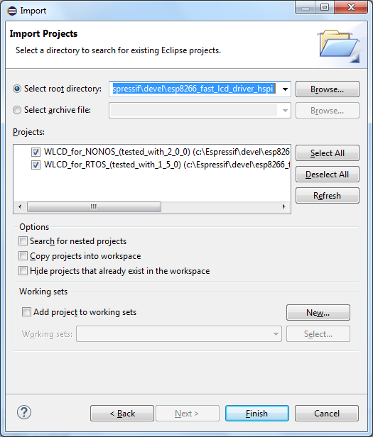
4] open Eclipse, go to menu File -> Import ... and double-click on item "General->Existing Projects into Workspace". Then select root directory - the path where you've unzipped my repo ("c:\Espressif\devel\esp8266_fast_lcd_driver_hspi"), click Finish


5] before you compile! (if you're going to compile "NON-OS" version)
- we need to update the Espressif's eagle_soc.h, because it's not complete. More complete definition was created by me using "pin_mux_register.h" from RTOS SDK. We need this to be able to work with ESP8266's HSPI interface. So make a backup of original "c:\Espressif\ESP8266_SDK\include\eagle_soc.h" and overwrite it with "...\modified_NONOS_SDK_files_(overwrite_original)\include\eagle_soc.h"
- we need to copy "...\modified_NONOS_SDK_files_(overwrite_original)\include\espmissingincludes.h" into "c:\Espressif\ESP8266_SDK\include". This is because Espressif even in new SDK 2.0.0 still don't include quite basic things we could also use. This problem is well known and espmissingincludes.h is handy, that's why we're copying it directly into SDK directory
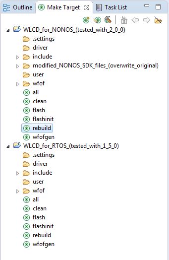
6] at last! double-click rebuild. Everything should be compiled without errors and you should end up with *.bin files in "...\firmware" directory

Note: the "official" *.mk of the Devel Kit was modified:
common_nonos.mk:
- added target wfofgen (to create files "...\wfof\wfof_data.h" and "...\wfof\wfof_idxs.h") which in combination with WFOF system will provide access to data of additional binary files
- added "include/driver" to EXTRA_INCDIR
- altered flashinit for 1 MB FLASH size
common_rtos.mk:
- added target wfofgen (to create files "...\wfof\wfof_data.h" and "...\wfof\wfof_idxs.h") which in combination with WFOF system will provide access to data of additional binary files
- added "include/driver" to EXTRA_INCDIR
- fixed eagle.irom0text.bin offset to 0x20000 (this is what's in original RTOS SDK 1.5.0. ld script "eagle.app.v6.ld")
- altered flashinit for 1 MB FLASH size
7] flash the *.bin files into the FLASH memory using your favourite programmer (you've done the step 2] successfully, didn't you?)
(for NON-OS SDK, as defined in ld script)
eagle.flash.bin-------->0x00000
eagle.irom0text.bin---->0x10000

(for RTOS SDK, as defined in ld script)
eagle.flash.bin-------->0x00000
eagle.irom0text.bin---->0x20000
8] if you've connected the LCD to the ESP8266 (see section "Connection with LCD controller" above) and everything is working ok, you should see the WLCD demo on the display (if not, see next step)
9] if you don't see the WLCD demo properly, try to play with main settings in "...\include\driver\wlcd.h". Try to decrease the speed / change color depth / ... then repeat steps 6], 7]
Especially these are important (there are more, but start with these):
//==== main config of WLCD (edit only here)
#define WLCD_DISPLAY			WLCD_ILI9488 //choose one of supported LCD controllers
#define WLCD_BPP				WLCD_18BPP   //choose one of supported color depths - ! WLCD images must correspond
#define WLCD_PANEL_BGR_ORDER	1            //0 - default, LCD panel has RGB order; 1 - LCD panel has BGR order (is not related to data shifted via SPI - there's still RGB order)
#define	WLCD_USE_HSPI                        //use ESP8266's HSPI interface to communicate with LCD much faster. Comment the definition to use SW bit-banging - interface pins remain the same (see wlcd_init() for pin description)
#define WLCD_SPI_CLK_PREDIV		1            //HSPI CLK = CPU_CLK_FREQ (80 MHz by default) / (SPI_CLK_PREDIV*SPI_CLK_CNTDIV) => 80 / 2 = 40 MHz
#define WLCD_SPI_CLK_CNTDIV		2            // ... (20 MHz: PREDIV=2, CNTDIV=2; 40 MHz: PREDIV=1, CNTDIV=2 (! not 2, 1); 80 MHz: PREDIV=1, CNTDIV=1)
//#define WLCD_NO_READ                       //uncomment this if the interface doesn't support reading operations - wlcd_img_get(...) will do nothing and return 0 (KeDei 3.5" LCD module uses shift registers => is unidirectional)
//==== (don't edit below this point)